I compared the results of Renesas' Thermocouple appnote's firmware for the Road test: Renesas Solution Starter Kit for RX23E-A. This is a first step to check (and learn) the analogue capacities of the RX23E-A.
All drawings and schematic snippets come from the starter kit user manual and its thermocouple application note. Photos and screen captures are mine.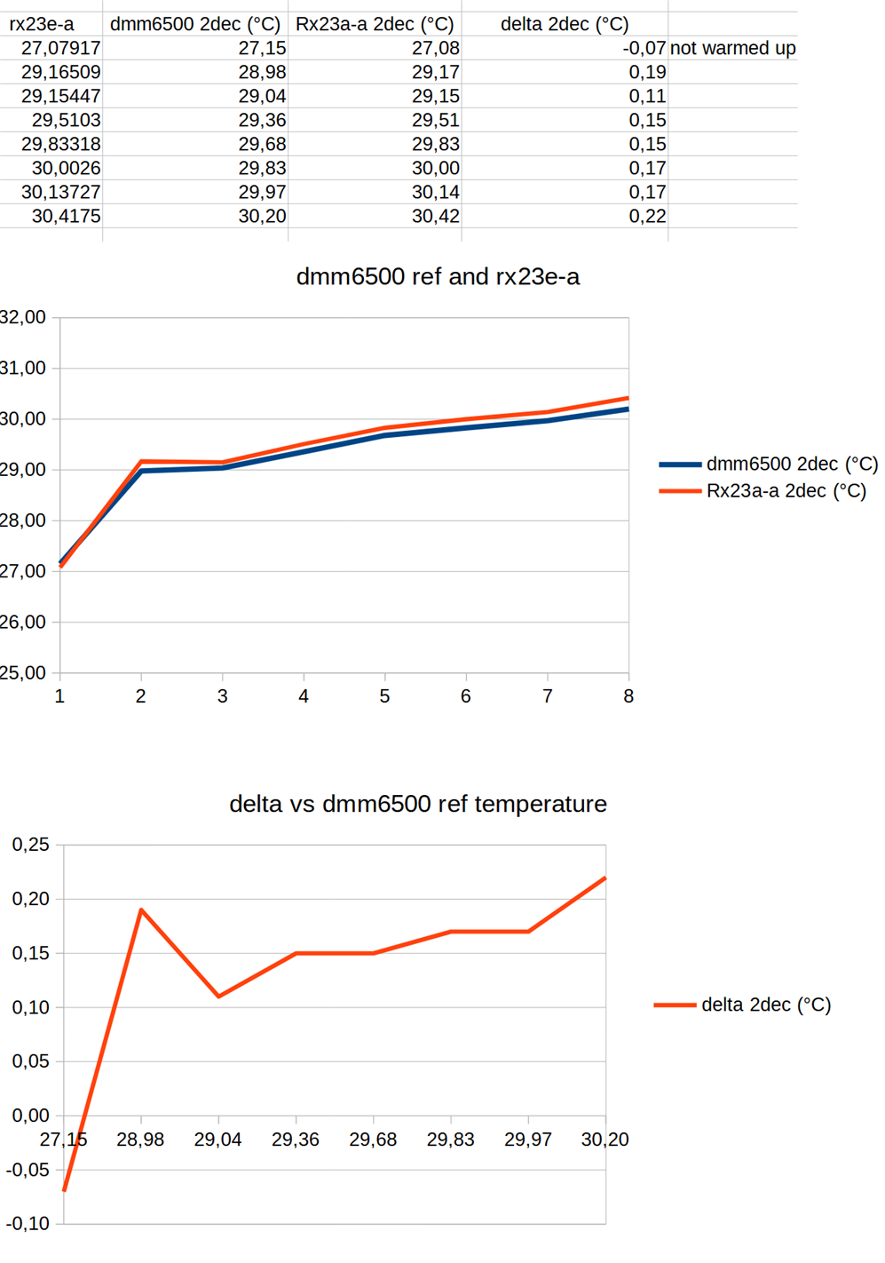
Test setup

I'm comparing the starter kit's measurement with those of a Keithley DMM6500. Both use a K-type thermocouple. And both use the same principle for cold junction compensation: a pt100 RTD. I put the two thermocouples in a little cardbox, so that they would be at a very similar temperature. It is not isolated, but it's creates a similar condition for the 2 probes, and avoids that draft and other conditions affects one of the two probes differently than the other.
These are the jumper settings. They use the on-board pt100 in 4-wire mode: 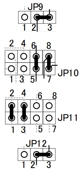 .
.
Connect the thermocouple. You can't do that wrong.
My test setup is very similar to the one that Renesas uses in their appnote. Starter kit setup is identical. They use an RTD and DMM for reference, where I use a compensated K-type and DMM. Their thermostatic chamber is my carton box. 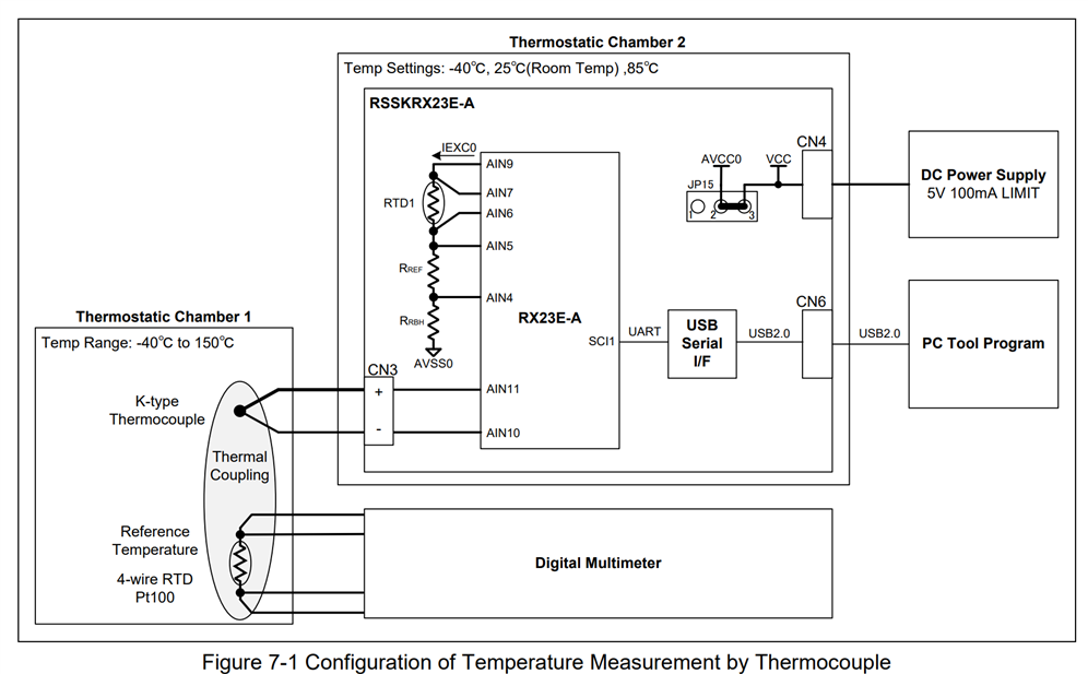
RX23E-A starter kit cold junction compensation approach
I've written a blog about the DMM6500 junction compensation. Let's focus on how Renesas deals with the subject.
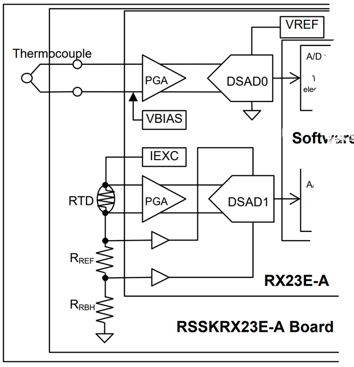
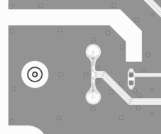
They have a pt100 RTD located very close to the cold junction. It sits on a decent body of copper together with the thermocouple connector (the cold junction location). It 'll have a very similar temperature.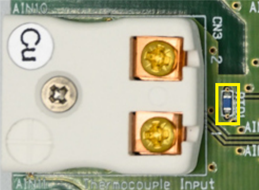
The 500 µA current through the RTD is delivered by one of the microcontroller's current sources. A sense resistor is in series with it acts as the ADC voltage reference, and another resistor (bottom headroom) that lifts the voltage of the sense resistor a bit away from ground, to an ideal level for the buffer and ADC.
The voltage over the RTD goes via a programmable gain amp to the ADC. The voltage over the current amp is buffered and goes to that ADC's reference. RRBH is 390R, RREF 5K1. RTD is a Vishay PTS060301B100RP100 . Because the current through the RTD is exactly the same as the one through the voltage reference for its ADC, drift is mitigated.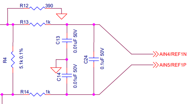
The RTD bottom connection is coming in at the R4 / R14 junction. Its top pin is connected to the current exciter.
Then they sample it, and it's over to the firmware. The flow below describes what happens with RTD and thermocouple measurements.
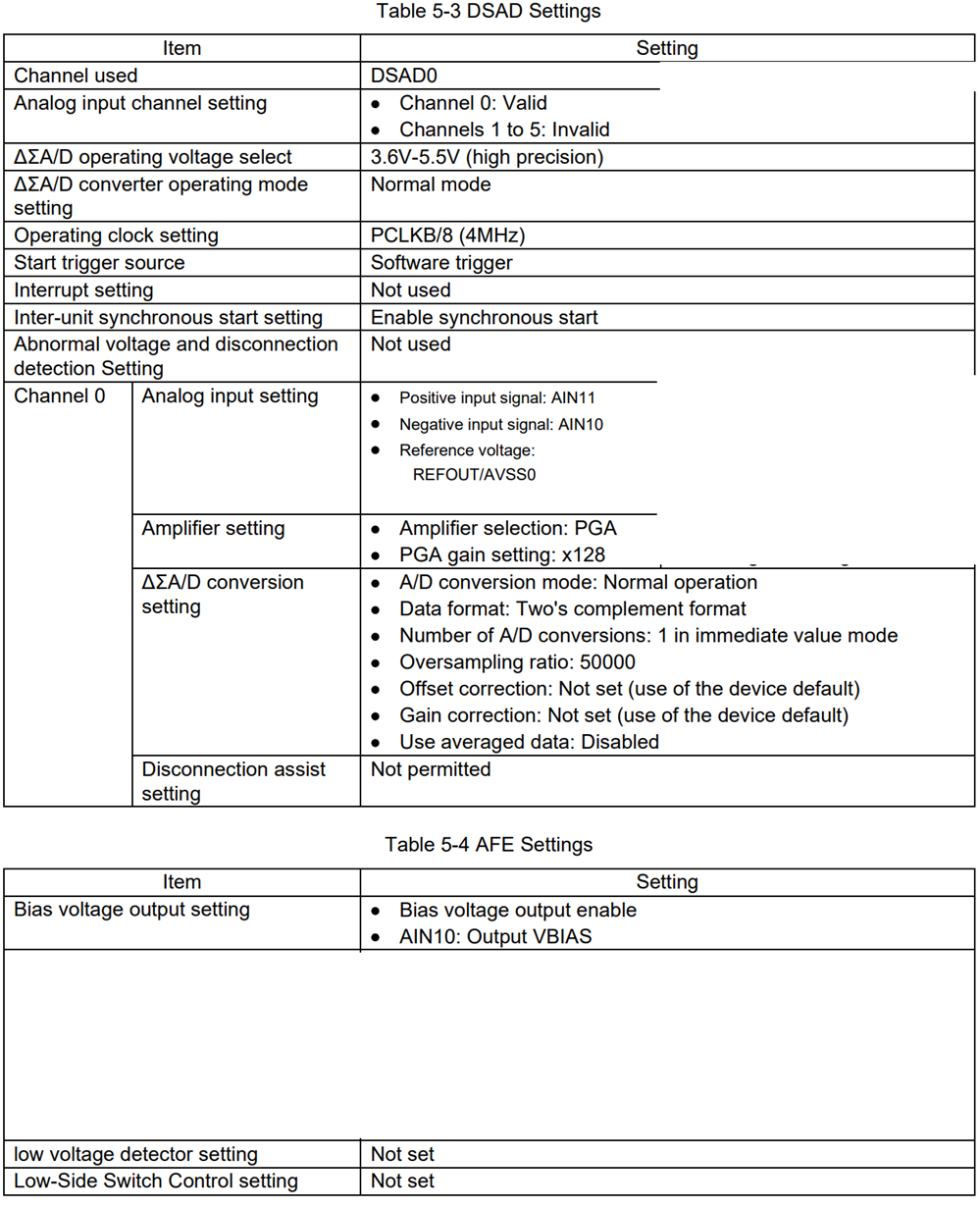
I'm not going to elaborate on that in today's blog. I'll write another one that focuses on calculations and algorithms. Let's look how the ADCs and analogue front ends are configured:
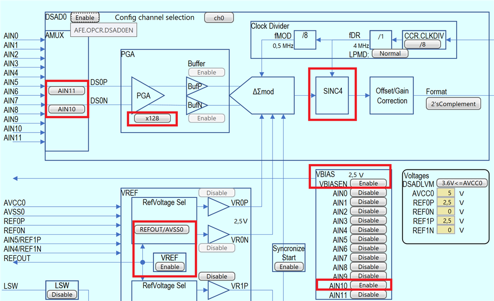
Configurations for the thermocouple
front end amplification is 128. The thermocouple gets a 2.5 V bias.
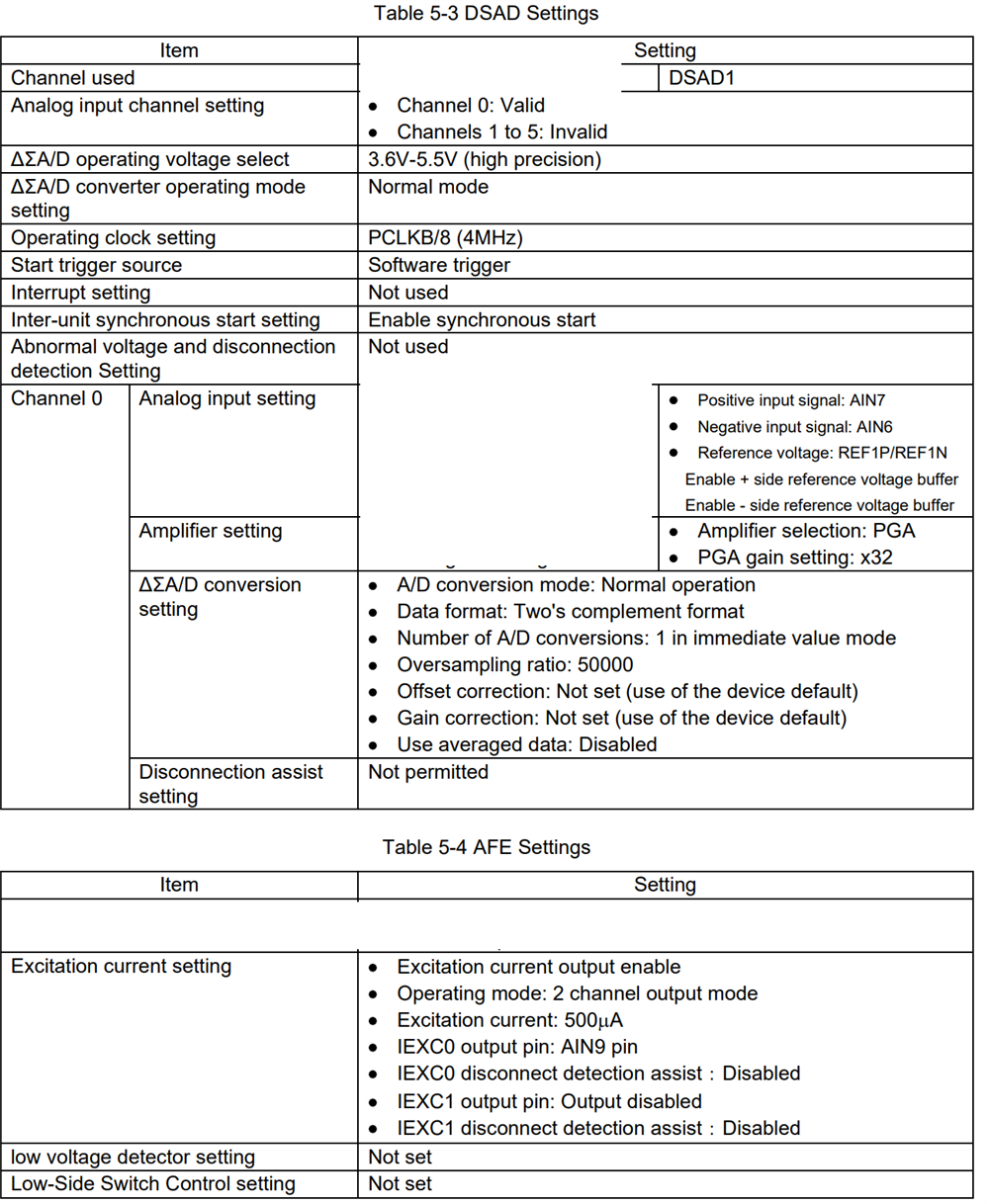
Configurations for the RTD
Front end amplification is 32x. Also spot the side references for the current through the RTD. Current exciter 0 delivers 500 µA current for the RTD circuit.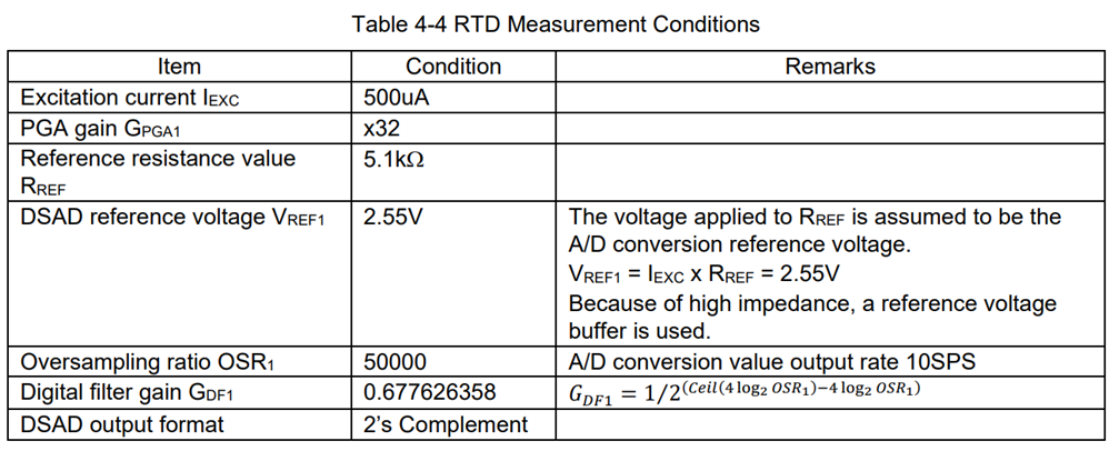
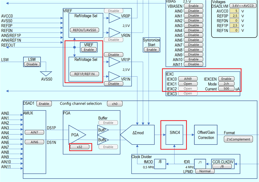
The voltage reference buffers for VREF show disabled here. Thhat's a bug in the PC Tool. They are enabled.
Findings
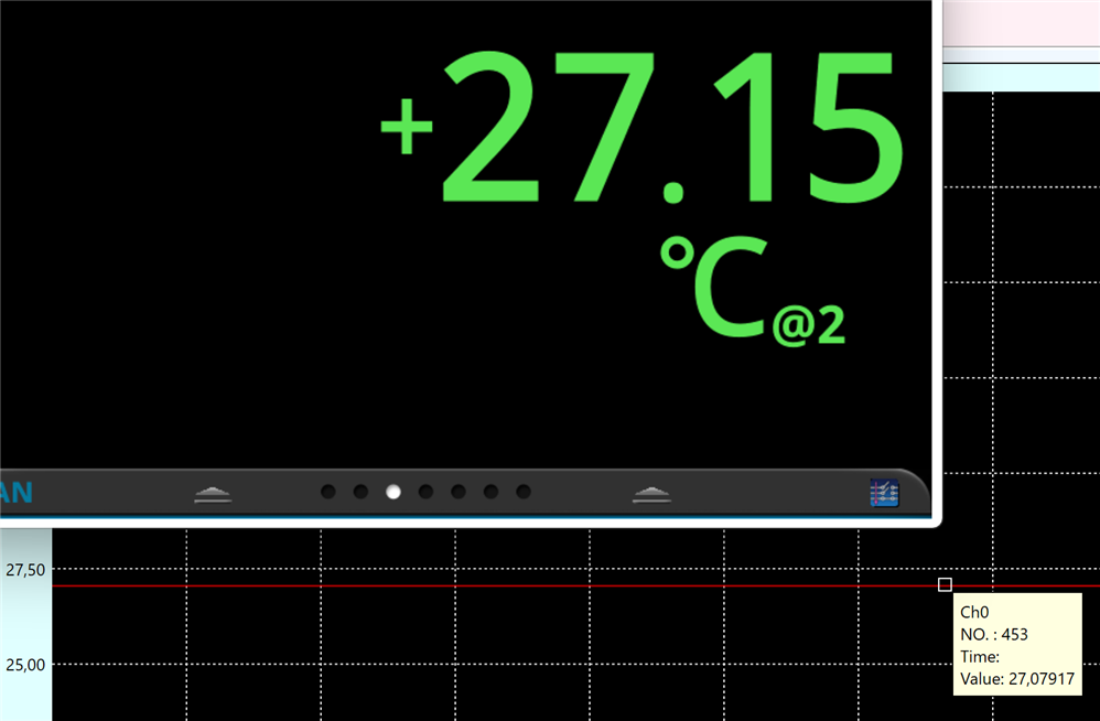
That the two devices report very similar temperatures (max 0.2°C apart) may be more coincidence than science. I didn't perform the starter kit's calibration process. When temperature changed - I measured between 20° and 32°C - the two devices stayed within the same delta.

Top Comments