The 16 pin DIP component looks like a MAX232 chip. If you look at the datasheet for that component you will see a T1 in Connection (possibly pin 11).
If you pull out the IC and push a prototyping wire into the socket at that pin, you can connect the other end to your MCU. The communication should then take place at TTL level.
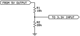
You will also need to level-shift the 5v on the rfid board to 3.3v for your Freescale board.
The 16 pin DIP component looks like a MAX232 chip. If you look at the datasheet for that component you will see a T1 in Connection (possibly pin 11).
If you pull out the IC and push a prototyping wire into the socket at that pin, you can connect the other end to your MCU. The communication should then take place at TTL level.
You will also need to level-shift the 5v on the rfid board to 3.3v for your Freescale board.