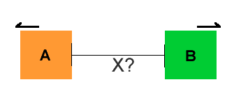
By mounting a laser on the far edge of block A, a reflecter on block B and a detecter on the near side of block A. Assuming stability of the blocks, the distance between the laser and the detector sets the stop point. (distance between blocks)
Another method that could be used in conjunction with billpenner's reflection / triangulation method is laser pulse generation. A rapid pulse is needed, and if you measure the rise time on the pulse, and the rise time on the reflected / detected pulse, you can calculate distance through phase difference.
Quick calculations / thoughts
Speed of light in a vacuum: 299798458 metres per second (c - 90 for light speed through air)
So, 1 / (299798458 - 90) = 3.335575196 nS per metre.
Therefore, if you want to measure with metre accuracy, you'd have to have pulse detection down to 3.3nS. 10cm? 330pS. Hmm... What you might be able to do is generate a longer pulse, but proportional to the received pulse difference duration. This scaling might also allow for tuning. 1GHz / 1nS isn't so difficult to build for, maybe 2, so this approach might be doable.
It would also translate well to longer distances, where trigonometric methods would have to measure increasingly shallow angles - on the contrary here, the pulse delay is longer, and therefore easier to detect.
Of course, if you're doing this with a reflector, 3.33nS would give you 50CM resolution, as the light will travel there then back - an increase of 1M distance then means 2M extra round trip. Again, doubling the time makes it a bit easier to detect perhaps.
My apologies - I came straight to the 2nd page! Laser interferometry too expensive then... Ok, well using a laser pointer as a previous poster suggested, with a reflector, might be the way forward. As the blocks are also fairly close, an old barcode scanner might be an ideal source of parts; The internals often use a sensor that's effectively a single line cmos / ccd camera. This could be used to determine the angle of reflection quite easily, and also be an easily adjustable / configurable solution.
Ultrasonics might be a good way forward too, but you could also use an LED driven by a tone generator - a phototransistor might then be used to determine distance based on either amplitude of the reflected signal, or angle, dependent on placement / focus / surface reflectivity.
Further to the above, the PIC24F64GB004 (and others) have a CTMU peripheral. This is capable of 1nS resolution & generating pulses asyncronously w.r.t. the internal clock. So, laser ranging may still be possible on a budget! (1M = 2M round trip of 6.6nS, therefore 1 / 6.6 = 15.15CM resolution @ 1nS) Perhaps not for the 250 microns you'd ideally like for your setup though. 
Billpenner & Frost,
I like the lasr range finder option most. Although I was looking for a simpler answer, I think this may work out well.
Some thoughts on how to actually build such a device? If it isn't too expensive, I will attempt to build it.
The theory:
Distance = h / tan(theta)
This is what you are proposing?
Cabe
Hi Cabe,
A very simple approach is to set up two laser pointers set up to hit the same spot at only the correct distance. As you move one box towards the other, the two laser spots will converge. If you move them away, the spots diverge. The approach is simple, you can reset the distance to just about any range where the laser spots are still visible and best of all, its nearly fool proof.
By the way, the British used a similar system to set the altitude for thier bombers when they bombed the Ruhr river dams in Germany.
Thanks
DAB
Your picture is pretty much what I thought, except the laser would need to be set at angle theta, on the "source" block. Movments on the target block away / towards source would then change where the reflected laser point hit the target.
Either way, you've got a mirror / reflector / angle problem to solve. Setting theta for the laser shouldn't be too hard - simply accurately measure a right angled triangle inside a large room, the triangle is of known proportions, bingo, you've got a known theta.
The other way is to get a reflector set at angle theta on the target block. A little bit harder, and if it's moving, it may change the angle and destroy accuracy. If you use a flat mirror on the target, it's probably simpler all round.
Anyway, it looks like the final calc is going to be distance = (h/2) / tan(theta) as your diagram would appear to show the beam reflecting off a surface with a mirror set at theta degrees.
So, detecting where the laser pointer hits is the last problem to solve. Preferably, I suppose you'd use as few optical components as possible as that way is going to be expensive, due to accuracy depending on quality and ability to set correctly. Simplest option I can think of is to print off a scale on a laser printer / A4 paper, and use this for the beam to hit and for a camera to see. Software can then determine where the beam is hitting, maybe even without a printed scale, and convert to distance.
In my opinion, using software to do the bulk of the work is going to be the best / cheapest way in terms of physical cost, apart from perhaps time. All you'd need to do though is detect at what point the colour thresholds exceed a certain value, in the X and Y planes. A camera looking at the back of the sheet of paper should do this ok. Classes are available in both .NET and Java to do this, depending on your preference.
For more accuracy this way, the simplest method is to make angle theta more obtuse, therefore affecting h more over a given distance. To calibrate such a device, measure distance D at two points with calipers, and then mark the spot positions (in software / on paper / however) as required. Determining distance between these two points should be a simple matter of interpolation.
Hey DAB
I like this approach! This way the lasers can be mounted on the extreme of the outside of block A and the stability of block B is not as much a problem.
The distance is simple to calculate (displacement of dots). However, there is no way to calculate the negative, since a distance beyond the convergence of the dots will be the same result as the positive. For a little more sophistication a linear diode array mounted on block B would provide a direct readout of distance.
Bill
DAB
Another thought... if plus/minus is imporant , two different color lasers and filters on the linear arrays would allow diferentation of plus & Minus.
Hi Bill,
It would be easier to just use a video camera and compare the dot positions from frame to frame. That way you get both position and direction for each laser pointer. Remember, Keep It Simple if you want something to work.
Thanks,
DAB
Range finder electronics exists as packages ready to integrate. Just choose your distance, short is ultrasonic, long is laser. Examples:
http://analogmodules.com/products/lrf-receivers.php