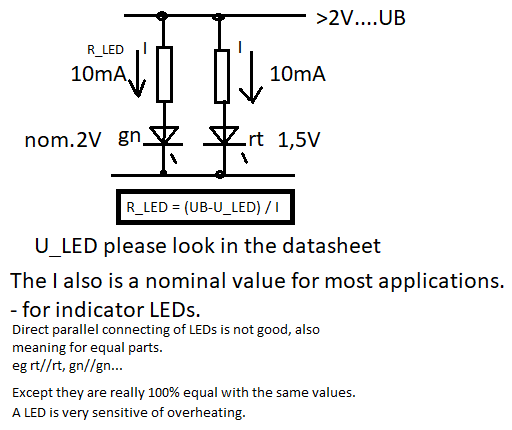
I have a need to connect a number of LED's in parallel. Can someone share their insight into why an additional resistor is required for the LED's of different colour in parallel to light?
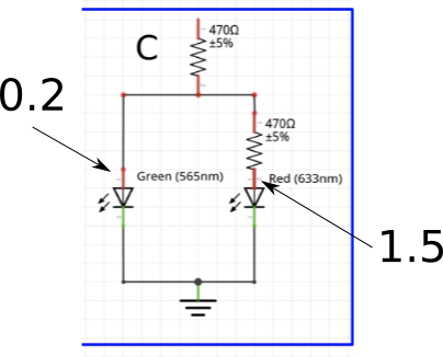
The LED's in circuit A lights with no issues. In circuit B, only the Red LED lights. Circuit C lights both LED's but requires the extra resistor to achieve the success.
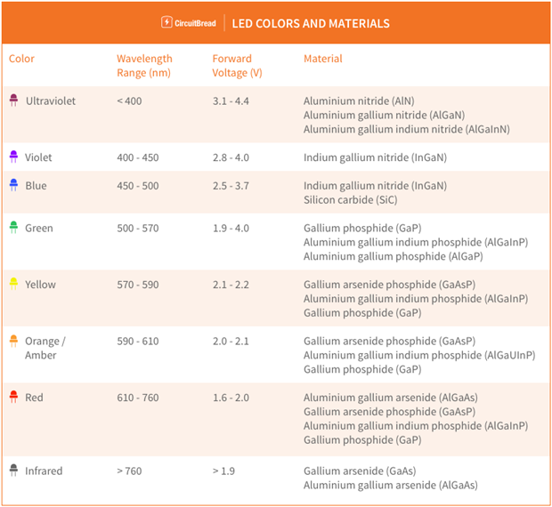
My formal electronics training occurred when vacuum tubes were still common in electronics. My understanding would be voltage drops. The Green LED requires a higher voltage drop to light than a Red LED. Circuit B doesn't light because the Red LED lights with it's voltage drop not being sufficient for Green to light.
I appreciate this is a pretty simplistic circuit. I find for myself exploring the basics refreshes the knowledge retained in my magnetic core memory:)