element14 Community
element14 Community
    Register Log In
  • Site
  • Search
  • Log In Register
  • Community Hub
    Community Hub
    • What's New on element14
    • Feedback and Support
    • Benefits of Membership
    • Personal Blogs
    • Members Area
    • Achievement Levels
  • Learn
    Learn
    • Ask an Expert
    • eBooks
    • element14 presents
    • Learning Center
    • Tech Spotlight
    • STEM Academy
    • Webinars, Training and Events
    • Learning Groups
  • Technologies
    Technologies
    • 3D Printing
    • FPGA
    • Industrial Automation
    • Internet of Things
    • Power & Energy
    • Sensors
    • Technology Groups
  • Challenges & Projects
    Challenges & Projects
    • Design Challenges
    • element14 presents Projects
    • Project14
    • Arduino Projects
    • Raspberry Pi Projects
    • Project Groups
  • Products
    Products
    • Arduino
    • Avnet & Tria Boards Community
    • Dev Tools
    • Manufacturers
    • Multicomp Pro
    • Product Groups
    • Raspberry Pi
    • RoadTests & Reviews
  • About Us
  • Store
    Store
    • Visit Your Store
    • Choose another store...
      • Europe
      •  Austria (German)
      •  Belgium (Dutch, French)
      •  Bulgaria (Bulgarian)
      •  Czech Republic (Czech)
      •  Denmark (Danish)
      •  Estonia (Estonian)
      •  Finland (Finnish)
      •  France (French)
      •  Germany (German)
      •  Hungary (Hungarian)
      •  Ireland
      •  Israel
      •  Italy (Italian)
      •  Latvia (Latvian)
      •  
      •  Lithuania (Lithuanian)
      •  Netherlands (Dutch)
      •  Norway (Norwegian)
      •  Poland (Polish)
      •  Portugal (Portuguese)
      •  Romania (Romanian)
      •  Russia (Russian)
      •  Slovakia (Slovak)
      •  Slovenia (Slovenian)
      •  Spain (Spanish)
      •  Sweden (Swedish)
      •  Switzerland(German, French)
      •  Turkey (Turkish)
      •  United Kingdom
      • Asia Pacific
      •  Australia
      •  China
      •  Hong Kong
      •  India
      • Japan
      •  Korea (Korean)
      •  Malaysia
      •  New Zealand
      •  Philippines
      •  Singapore
      •  Taiwan
      •  Thailand (Thai)
      • Vietnam
      • Americas
      •  Brazil (Portuguese)
      •  Canada
      •  Mexico (Spanish)
      •  United States
      Can't find the country/region you're looking for? Visit our export site or find a local distributor.
  • Translate
  • Profile
  • Settings
Experts, Learning and Guidance
  • Technologies
  • More
Experts, Learning and Guidance
Ask an Expert Forum XTAL clock and 2A03
  • Blog
  • Forum
  • Documents
  • Leaderboard
  • Files
  • Members
  • Mentions
  • Sub-Groups
  • Tags
  • More
  • Cancel
  • New
Join Experts, Learning and Guidance to participate - click to join for free!
Actions
  • Share
  • More
  • Cancel
Forum Thread Details
  • Replies 17 replies
  • Subscribers 302 subscribers
  • Views 4516 views
  • Users 0 members are here
  • nintendo entertainment system
  • adruino
  • retro gaming console
Related
See a helpful answer?

Be sure to click 'more' and select 'suggest as answer'!

If you're the thread creator, be sure to click 'more' then 'Verify as Answer'!

XTAL clock and 2A03

splatkillwill
splatkillwill over 5 years ago

I'm not sure where to ask this but I'm a newbie and I'm looking for someone to look over a schematic before I try it so I don't break anything (specifically a 2A03 (6502 based NES CPU) I only have one). The idea is to hook enough of it up to get it running and interact with it with a Adruino Uno. The Adruino only has enough pins to look at the lower 8 bits of the address bus but I figure when I get to the Adruino script I can just respond to the $fc and $fd of the $fffc and $fffd reset vector and not send any JMP instructions to anything lower that $ff00 to get started poking around.

image

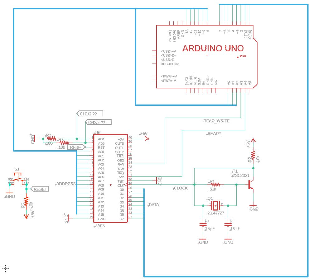
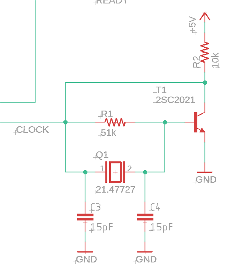
I'm specifically worried about the XTAL clock. Its based on StandaloneNesPlayer (soniktech.com) but I don't have a 74HCT04N so I figured I'd use a transistor for the not gate but my R2 value of 10k is arbitrary.

image

I attached the Eagle project (I'm new at that too)

Attachments:
my_NES.zip
  • Sign in to reply
  • Cancel

Top Replies

  • michaelkellett
    michaelkellett over 5 years ago +3
    I don't think this oscillator will work. Use the recommended chip (or a ready made oscillator). BUT..... you seem to connecting the Arduino to the NES chip as if the Arduino were a memory device - what…
  • Jan Cumps
    Jan Cumps over 5 years ago in reply to splatkillwill +3
    The oscillator in the original article is a Pierce oscillator.
  • jc2048
    jc2048 over 5 years ago +3
    As Michael says, you'll find this tricky to get right without some way of looking at the waveform coming out. This worked with an ordinary 16MHz AT-cut processor crystal and a 2N3904 transistor. I've biased…
  • michaelkellett
    michaelkellett over 5 years ago

    I don't think this oscillator will work.

    Use the recommended chip (or a ready made oscillator).


    BUT..... you seem to connecting the Arduino to the NES chip as if the Arduino were a memory device - what makes you think this can work ?


    MK

    • Cancel
    • Vote Up +3 Vote Down
    • Sign in to reply
    • Cancel
  • splatkillwill
    splatkillwill over 5 years ago in reply to michaelkellett

    Thanks for the feedback. Recommended by whom? The 21.47727 xtal is the original one from the same board the 2A03 is from. I guess I should use the original boad as an example for the *** circuit rather then that link. I'll try to map that out then re-evaluate.


    The idea was that the Adruino is faster (16MHz) then then 2A03 (~1MHz) so could use the readwrite line as an inturupt so when ever it goes high it triggers the Adruino to output on the 8 digital pins connected to the data bus, the next instuction or value I want to send to the 2A03 and at idle just send NOP then JMP to some starting address in a loop.


    If the timing of all that doesn't / won't work I could hard code NOP just to see if the 2A03 is working.

    • Cancel
    • Vote Up +2 Vote Down
    • Sign in to reply
    • Cancel
  • Jan Cumps
    Jan Cumps over 5 years ago in reply to splatkillwill

    The oscillator in the original article is a Pierce oscillator.

    • Cancel
    • Vote Up +3 Vote Down
    • Sign in to reply
    • Cancel
  • michaelkellett
    michaelkellett over 5 years ago in reply to splatkillwill

    Do you have a logic analyser or an oscilloscope - if not then you have pretty much no chance of getting this working.


    The Arduino is nothing like fast enough for this to work. I couldn't find timing information for the 2A03 but assuming it's like a 6502:

    At 1MHz cpu clock you get 575ns read access time - about 9 processor cycles, during which time the AVR processor would need to

    respond to an interrupt, set the bus direction, read the address, output the data and return from the interrupt.

    It isn't fast enough, even if coded in assembler.


    You could do it with a much faster processor but you would need to code it very carefully in assembler or C (not using Arduino environment).

    An ST STM32F42x could do it, and could probably provide a suitable if not exact clock as well.

    The NUCLEO-F429ZI (about £20) from Farnell would do nicely, the processor has 256k of RAM and clocks at up to 180MHz.

    The coding will be non trivial - you won't be able to use the HAL routines provided by ST to operate the IO ports but will need

    to code with direct access to the STM32F429 registers directly.


    Once again, you'll need to be able to look at signals to get this working.


    MK

    • Cancel
    • Vote Up +2 Vote Down
    • Sign in to reply
    • Cancel
  • Jan Cumps
    Jan Cumps over 5 years ago in reply to Jan Cumps

    Jan Cumps  wrote:


    The oscillator in the original article is a Pierce oscillator.

    It's the month of Project14 | Making Time: Anything that Uses or Alters Time such as Clocks, Timers, Egg Timers, and More! .

    I'm going to try and make a single transistor Pierce oscillator. I've got a candidate design from a Linear Technology application note.

    I've built one up on perfboard this morning, but haven't tested it yet.

    image

    • Cancel
    • Vote Up +2 Vote Down
    • Sign in to reply
    • Cancel
  • michaelkellett
    michaelkellett over 5 years ago in reply to Jan Cumps

    Very coolly opportunistic !


    I miss the nice old fashioned crystal cans - the little surface mount ones just don't have the same feel !


    MK

    • Cancel
    • Vote Up +1 Vote Down
    • Sign in to reply
    • Cancel
  • Jan Cumps
    Jan Cumps over 5 years ago in reply to michaelkellett

    michaelkellett  wrote:


    Very coolly opportunistic !


    Yes image.


    It works:

    image

    • Cancel
    • Vote Up +2 Vote Down
    • Sign in to reply
    • Cancel
  • michaelkellett
    michaelkellett over 5 years ago in reply to Jan Cumps

    Is it an optical/camera illusion but the 4 cycles on the left lean to the left and the three on the right lean to the right !


    BTW - the app note you linked is from National Semiconductors (now part of TI). Linear technology, another good US analogue semi

    company, now belongs to Analog Inc.


    In the good old days, (1970s) National were a real force - I still have some Data and Applications books from then.


    MK

    • Cancel
    • Vote Up +1 Vote Down
    • Sign in to reply
    • Cancel
  • Jan Cumps
    Jan Cumps over 5 years ago in reply to michaelkellett

    The leaning is a camera artifact.

    This is a scope capture, with a 16 MHz crystal this time.

    image

    It's far from a perfect sine wave (for curiousity I turned on the FFT and there's a whole train of harmonics).

    image

    But the wave form is not the point here. It's a clock.

    • Cancel
    • Vote Up 0 Vote Down
    • Sign in to reply
    • Cancel
  • michaelkellett
    michaelkellett over 5 years ago in reply to Jan Cumps

    Certainly, I don't know if the 2A03 cares about getting a good square wave on its clock input - I haven't been able to find  a spec for it.


    Which FET type did you use ?


    MK

    • Cancel
    • Vote Up 0 Vote Down
    • Sign in to reply
    • Cancel
>
element14 Community

element14 is the first online community specifically for engineers. Connect with your peers and get expert answers to your questions.

  • Members
  • Learn
  • Technologies
  • Challenges & Projects
  • Products
  • Store
  • About Us
  • Feedback & Support
  • FAQs
  • Terms of Use
  • Privacy Policy
  • Legal and Copyright Notices
  • Sitemap
  • Cookies

An Avnet Company © 2025 Premier Farnell Limited. All Rights Reserved.

Premier Farnell Ltd, registered in England and Wales (no 00876412), registered office: Farnell House, Forge Lane, Leeds LS12 2NE.

ICP 备案号 10220084.

Follow element14

  • X
  • Facebook
  • linkedin
  • YouTube