element14 Community
element14 Community
    Register Log In
  • Site
  • Search
  • Log In Register
  • Community Hub
    Community Hub
    • What's New on element14
    • Feedback and Support
    • Benefits of Membership
    • Personal Blogs
    • Members Area
    • Achievement Levels
  • Learn
    Learn
    • Ask an Expert
    • eBooks
    • element14 presents
    • Learning Center
    • Tech Spotlight
    • STEM Academy
    • Webinars, Training and Events
    • Learning Groups
  • Technologies
    Technologies
    • 3D Printing
    • FPGA
    • Industrial Automation
    • Internet of Things
    • Power & Energy
    • Sensors
    • Technology Groups
  • Challenges & Projects
    Challenges & Projects
    • Design Challenges
    • element14 presents Projects
    • Project14
    • Arduino Projects
    • Raspberry Pi Projects
    • Project Groups
  • Products
    Products
    • Arduino
    • Avnet & Tria Boards Community
    • Dev Tools
    • Manufacturers
    • Multicomp Pro
    • Product Groups
    • Raspberry Pi
    • RoadTests & Reviews
  • About Us
  • Store
    Store
    • Visit Your Store
    • Choose another store...
      • Europe
      •  Austria (German)
      •  Belgium (Dutch, French)
      •  Bulgaria (Bulgarian)
      •  Czech Republic (Czech)
      •  Denmark (Danish)
      •  Estonia (Estonian)
      •  Finland (Finnish)
      •  France (French)
      •  Germany (German)
      •  Hungary (Hungarian)
      •  Ireland
      •  Israel
      •  Italy (Italian)
      •  Latvia (Latvian)
      •  
      •  Lithuania (Lithuanian)
      •  Netherlands (Dutch)
      •  Norway (Norwegian)
      •  Poland (Polish)
      •  Portugal (Portuguese)
      •  Romania (Romanian)
      •  Russia (Russian)
      •  Slovakia (Slovak)
      •  Slovenia (Slovenian)
      •  Spain (Spanish)
      •  Sweden (Swedish)
      •  Switzerland(German, French)
      •  Turkey (Turkish)
      •  United Kingdom
      • Asia Pacific
      •  Australia
      •  China
      •  Hong Kong
      •  India
      • Japan
      •  Korea (Korean)
      •  Malaysia
      •  New Zealand
      •  Philippines
      •  Singapore
      •  Taiwan
      •  Thailand (Thai)
      • Vietnam
      • Americas
      •  Brazil (Portuguese)
      •  Canada
      •  Mexico (Spanish)
      •  United States
      Can't find the country/region you're looking for? Visit our export site or find a local distributor.
  • Translate
  • Profile
  • Settings
Experts, Learning and Guidance
  • Technologies
  • More
Experts, Learning and Guidance
Ask an Expert Forum Looking for help on how to wire a relay
  • Blog
  • Forum
  • Documents
  • Leaderboard
  • Files
  • Members
  • Mentions
  • Sub-Groups
  • Tags
  • More
  • Cancel
  • New
Join Experts, Learning and Guidance to participate - click to join for free!
Actions
  • Share
  • More
  • Cancel
Forum Thread Details
  • State Suggested Answer
  • Replies 5 replies
  • Answers 4 answers
  • Subscribers 303 subscribers
  • Views 1324 views
  • Users 0 members are here
  • wiring
  • relay
Related
See a helpful answer?

Be sure to click 'more' and select 'suggest as answer'!

If you're the thread creator, be sure to click 'more' then 'Verify as Answer'!

Looking for help on how to wire a relay

bdohrn
bdohrn over 4 years ago

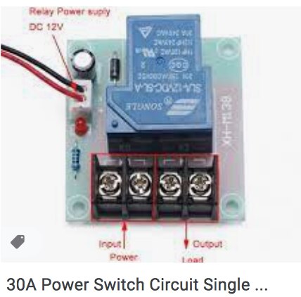
Below is a picture of a relay I purchased.  I want to use it to turn my inverter (connected to a 12v battery, provides 220 to a pump) on and off.


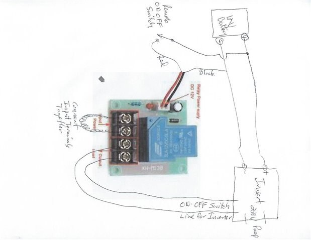
Unless you have a better idea, I think I should wire it into the inverter on/off switch somehow, but I am not sure what to wire to which terminal.

Secondly there are two terminals on the back of the inverter for the 12V battery cables. I assume that I should connect those to the two wires on the clip marked 12v. Do I just do that via some extra wires connecting from one to the other?


Help with how to wire this super appreciated. 

image

  • Sign in to reply
  • Cancel

Top Replies

  • dougw
    dougw over 4 years ago +3 suggested
    This is a simple way to implement the hysteresis function you want. This circuit takes a higher battery voltage to turn power on to the inverter than to turn power off. It is not clear at what voltage…
  • shabaz
    shabaz over 4 years ago +2 suggested
    Hi Beatrice, The simplest way in this situation is to just apply 12V DC to the red and black wires, and you'll hear a click. You can use a multimeter set to 'ohms' or to 'continuity' and 'buzz out' the…
  • colporteur
    colporteur over 4 years ago in reply to colporteur +2
    It has been a while since I dabbled in electronics drafting so I figured why not napkin out a drawing for you. Here is one way the relay module could be wired. The contacts inside the box are controlled…
  • colporteur
    0 colporteur over 4 years ago

    Rather difficult to identify operation of the relay from the picture.


    Can you translate the details from the relay and/or a name for the module?


    Typically you would have a normally open (N.O.), common (COM), normally close (N.C.) contacts. C is connected to N.C. without power. When the relay is triggered C is then connected to N.O.


    You only have two wire connections. The relay is either going to make the circuit or break the circuit.


    The relay could be configured to switch the Input side power to the output side power when the relay is engaged.

    • Cancel
    • Vote Up +1 Vote Down
    • Sign in to reply
    • Verify Answer
    • Reject Answer
    • Cancel
  • shabaz
    0 shabaz over 4 years ago

    Hi Beatrice,


    The simplest way in this situation is to just apply 12V DC to the red and black wires, and you'll hear a click.

    You can use a multimeter set to 'ohms' or to 'continuity' and 'buzz out' the connections.

    You'll find that one of the two screw terminals on the left, will only make an electrical connection with one of the two screw terminals on the right, when 12V is applied to the red and black wires.


    Or, you can try to follow the traces on the underside, and the relay will be wired such that the two terminals are in a 'double pole single throw' configuration, or 'single pole single throw' with two screw terminals hard-wired together. Your multimeter is your best friend though. If you don't have one, they cost less than $5 sometimes. But in the interim, you could try to follow the traces if you don't have a multimeter.


    Once you have determined which two screw terminals get connected together only when 12V is applied to the red/black wires, then you can attach those screw terminals in series with the inverter on/off switch that you mention.


    The red and black wires will connect to whatever you wish to use to control the relay.

    • Cancel
    • Vote Up +2 Vote Down
    • Sign in to reply
    • Verify Answer
    • Reject Answer
    • Cancel
  • jw0752
    0 jw0752 over 4 years ago

    Hi Beatrice,


    If you have access to the On-Off power switch of the inverter it may not be a high current circuit. Many inverters will internally use a low current circuit to switch the higher power circuit on and off. If this is a case you may not need a relay to turn the inverter on and off, just a regular switch. If you feel that you need the 30 Amp contacts of the relay here is a suggested circuit hookup that you can use.


    image

    Sorry the picture got flipped on it's side.


    John

    • Cancel
    • Vote Up +1 Vote Down
    • Sign in to reply
    • Verify Answer
    • Reject Answer
    • Cancel
  • colporteur
    0 colporteur over 4 years ago in reply to colporteur

    image


    It has been a while since I dabbled in electronics drafting so I figured why not napkin out a drawing for you. Here is one way the relay module could be wired. The contacts inside the box are controlled (i.e. move) when the 12V is applied to the module.


    As shabaz has suggested a multi-meter using the OHMS function to measure resistance will enable you to determine the contact mapping. You may discover A actually connects to D and not C when the relay is engaged.


    You may also discover that C & D are connected to the N.C. side of the relay and the circuit actually breaks contact between input and output when 12V is applied to the module.


    All of this can be discovered with the multi-meter and a supply to trigger the relay.


    You indicate a 220V pump. Check the rating on the relay contacts. They can be rated for 220V but typically 120V is more common. If the rating is lower you run the risk of burning the contacts when the relay is engaged, Burning to the point they may weld or not work because of the current draw.

    • Cancel
    • Vote Up +2 Vote Down
    • Sign in to reply
    • Verify Answer
    • Cancel
  • dougw
    0 dougw over 4 years ago

    This is a simple way to implement the hysteresis function you want.

    This circuit takes a higher battery voltage to turn power on to the inverter than to turn power off.

    It is not clear at what voltage the coil turns off - you will need to experiment.

    If the circuit is turning off at too low of a voltage, add more diodes in series with D4 until it turns off at the voltage you want.

    You will need to figure out which screw terminal to connect to the inverter - it will be C or D in colporteur diagram above.

    The relay switch input will be A in that diagram.

    The coil connections are marked DC 12V in your image. (Red is +)

    image

    • Cancel
    • Vote Up +3 Vote Down
    • Sign in to reply
    • Verify Answer
    • Reject Answer
    • Cancel
element14 Community

element14 is the first online community specifically for engineers. Connect with your peers and get expert answers to your questions.

  • Members
  • Learn
  • Technologies
  • Challenges & Projects
  • Products
  • Store
  • About Us
  • Feedback & Support
  • FAQs
  • Terms of Use
  • Privacy Policy
  • Legal and Copyright Notices
  • Sitemap
  • Cookies

An Avnet Company © 2025 Premier Farnell Limited. All Rights Reserved.

Premier Farnell Ltd, registered in England and Wales (no 00876412), registered office: Farnell House, Forge Lane, Leeds LS12 2NE.

ICP 备案号 10220084.

Follow element14

  • X
  • Facebook
  • linkedin
  • YouTube