Hey folks, I am working my way through Forrest Mims' Digital Logic Projects Workbook 2 and stumbling on understanding basic D-type flip-flop operations. I hope someone can help me understand where I am getting lost.
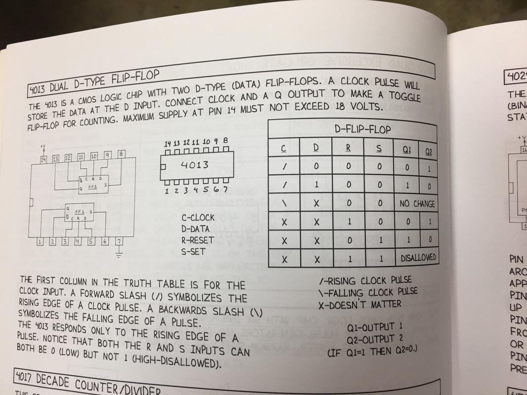
Mims presents this explanation of a 4013 D-type flip flop:
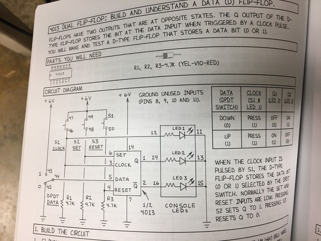
which, as I understand it, on the rising edge of a clock pulse Q1 gets set when D is set. (By the way, why does he use Q1 and Q2 in the truth table and Q and ~Q (I don't know how to write a Q with a line over it) in the schematic??). He presents a basic flip flop circuit to demonstrate this :
Ok I get when you set D in this circuit with the toggle switch manually, Q1 gets set high (1) with the rising clock pulse!
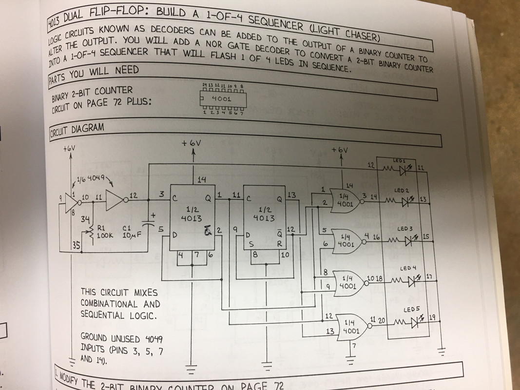
Now the circuit I am working on:
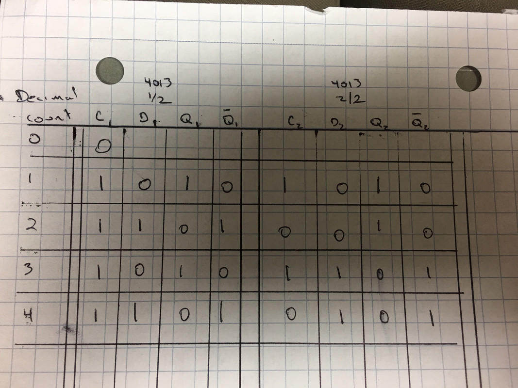
The circuit works as it should, lighting up LED's 1,2,3,4 in sequence. Ok. However, when I put a logic probe on pin 5 of the 4013 (D1) with the rising clock pulse starting from 0, D1 is 0 (low) but Q1 is 1 (high). I don't understand why Q1 is set when D1 is low. Here is the truth table I came up with but it seems to me from the truth table in the image at the top of this post, on rising clock pulse when D1 is 0, ~Q should get set to 1 (high). I feel like I am missing the sequence of how the outputs get changed but I don't know what... Help!
Thanks!
Robert Opalko
Message was edited by: Robert Opalko
Message was edited by: Robert Opalko


