Hi!
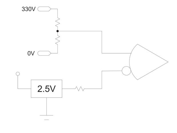
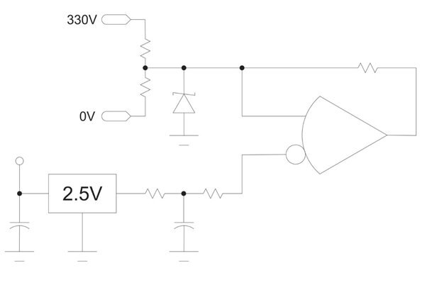
Do enyone know how i can make a led turn on that uses 3 volts, when a voltage has reached 330volts?
I am trying to make a indicator turn on when a capasitor is full..
Thanks for eny help! 
Be sure to click 'more' and select 'suggest as answer'!
If you're the thread creator, be sure to click 'more' then 'Verify as Answer'!
Hi!
Do enyone know how i can make a led turn on that uses 3 volts, when a voltage has reached 330volts?
I am trying to make a indicator turn on when a capasitor is full..
Thanks for eny help!