element14 Community
element14 Community
    Register Log In
  • Site
  • Search
  • Log In Register
  • About Us
  • Community Hub
    Community Hub
    • What's New on element14
    • Feedback and Support
    • Benefits of Membership
    • Personal Blogs
    • Members Area
    • Achievement Levels
  • Learn
    Learn
    • Ask an Expert
    • eBooks
    • element14 presents
    • Learning Center
    • Tech Spotlight
    • STEM Academy
    • Webinars, Training and Events
    • Learning Groups
  • Technologies
    Technologies
    • 3D Printing
    • FPGA
    • Industrial Automation
    • Internet of Things
    • Power & Energy
    • Sensors
    • Technology Groups
  • Challenges & Projects
    Challenges & Projects
    • Design Challenges
    • element14 presents Projects
    • Project14
    • Arduino Projects
    • Raspberry Pi Projects
    • Project Groups
  • Products
    Products
    • Arduino
    • Avnet Boards Community
    • Dev Tools
    • Manufacturers
    • Multicomp Pro
    • Product Groups
    • Raspberry Pi
    • RoadTests & Reviews
  • Store
    Store
    • Visit Your Store
    • Choose another store...
      • Europe
      •  Austria (German)
      •  Belgium (Dutch, French)
      •  Bulgaria (Bulgarian)
      •  Czech Republic (Czech)
      •  Denmark (Danish)
      •  Estonia (Estonian)
      •  Finland (Finnish)
      •  France (French)
      •  Germany (German)
      •  Hungary (Hungarian)
      •  Ireland
      •  Israel
      •  Italy (Italian)
      •  Latvia (Latvian)
      •  
      •  Lithuania (Lithuanian)
      •  Netherlands (Dutch)
      •  Norway (Norwegian)
      •  Poland (Polish)
      •  Portugal (Portuguese)
      •  Romania (Romanian)
      •  Russia (Russian)
      •  Slovakia (Slovak)
      •  Slovenia (Slovenian)
      •  Spain (Spanish)
      •  Sweden (Swedish)
      •  Switzerland(German, French)
      •  Turkey (Turkish)
      •  United Kingdom
      • Asia Pacific
      •  Australia
      •  China
      •  Hong Kong
      •  India
      •  Korea (Korean)
      •  Malaysia
      •  New Zealand
      •  Philippines
      •  Singapore
      •  Taiwan
      •  Thailand (Thai)
      • Americas
      •  Brazil (Portuguese)
      •  Canada
      •  Mexico (Spanish)
      •  United States
      Can't find the country/region you're looking for? Visit our export site or find a local distributor.
  • Translate
  • Profile
  • Settings
Experts, Learning and Guidance
  • Technologies
  • More
Experts, Learning and Guidance
Ask an Expert Forum Miller DX200 welder SEMIKRON SkiiP 33NEC125T2 Power IGBT Module
  • Blog
  • Forum
  • Documents
  • Leaderboard
  • Files
  • Members
  • Mentions
  • Sub-Groups
  • Tags
  • More
  • Cancel
  • New
Join Experts, Learning and Guidance to participate - click to join for free!
Actions
  • Share
  • More
  • Cancel
Forum Thread Details
  • Replies 97 replies
  • Subscribers 293 subscribers
  • Views 18607 views
  • Users 0 members are here
Related
See a helpful answer?

Be sure to click 'more' and select 'suggest as answer'!

If you're the thread creator, be sure to click 'more' then 'Verify as Answer'!

Miller DX200 welder SEMIKRON SkiiP 33NEC125T2 Power IGBT Module

mb443
mb443 over 3 years ago

imageThe hot topic for those who owns DX200 welder and willing to participate in re-implementing of the original PowerModule on discrete elements.

This is continuation of the discussion and efforts already put into at other forum:  Miller Boost Circuit Board Assembly NO. 200841

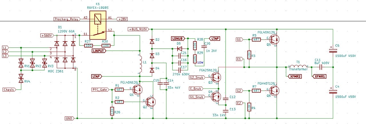
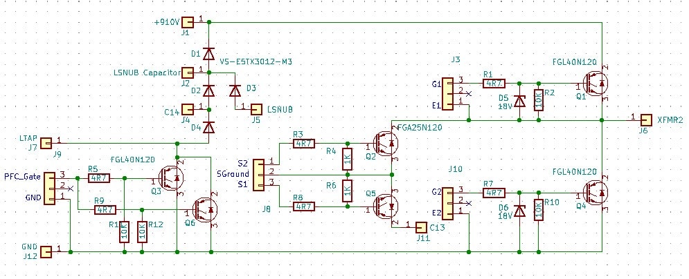
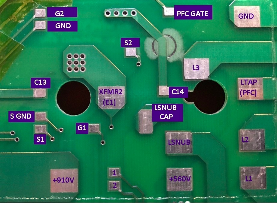
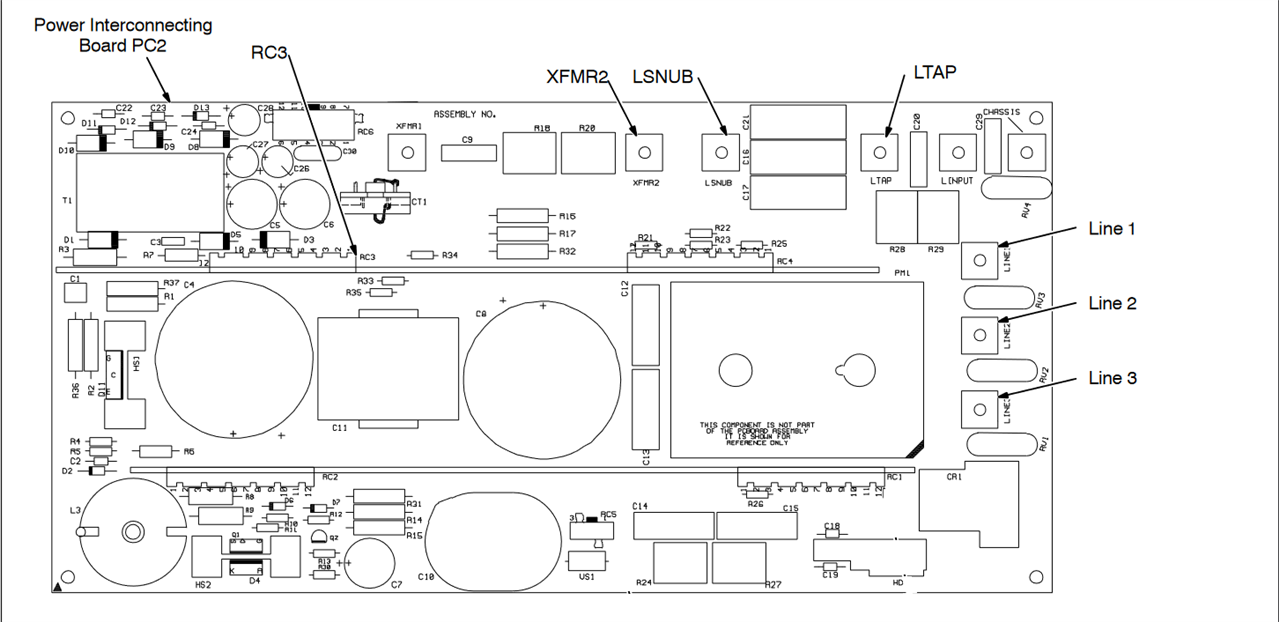
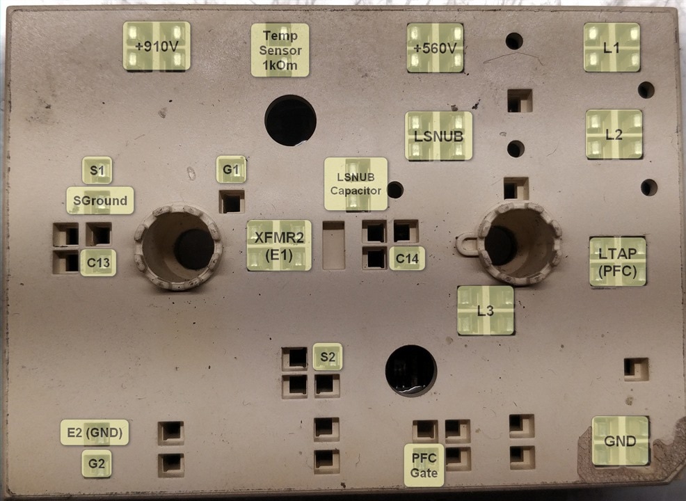
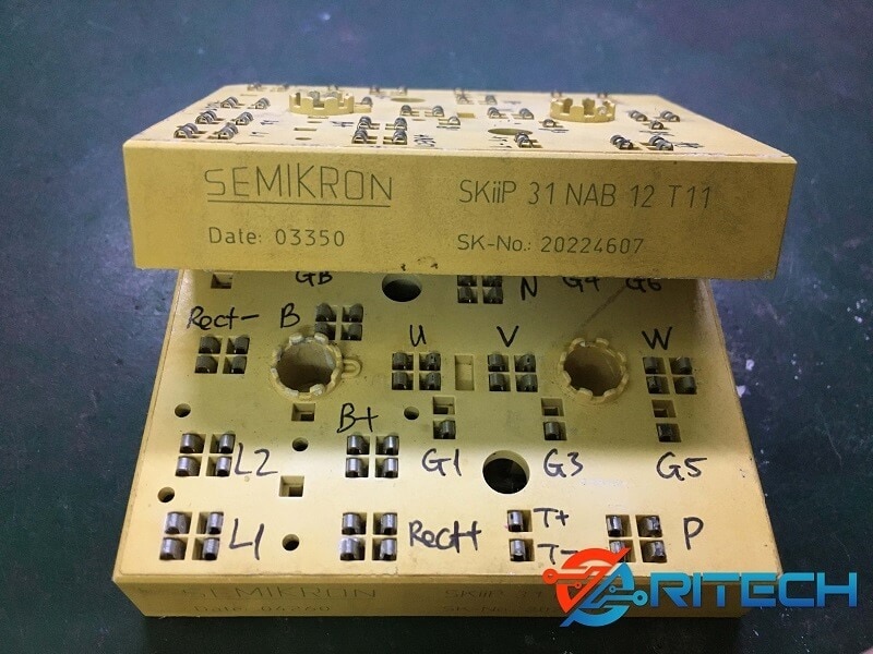
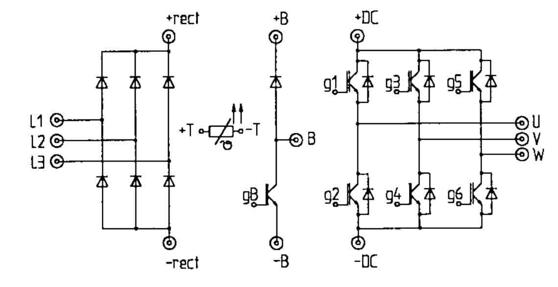
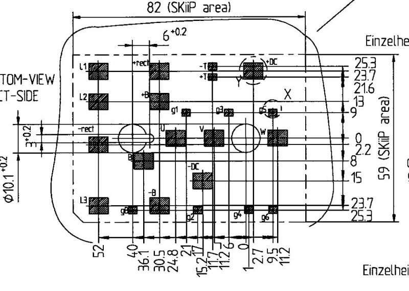
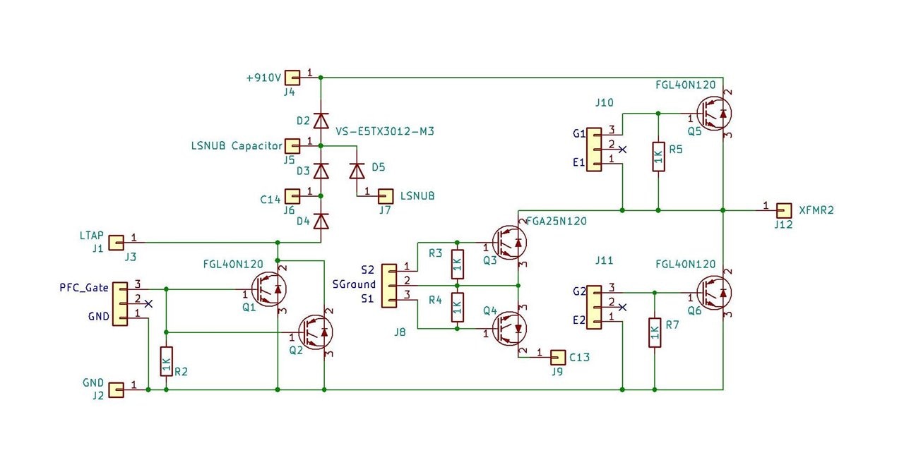
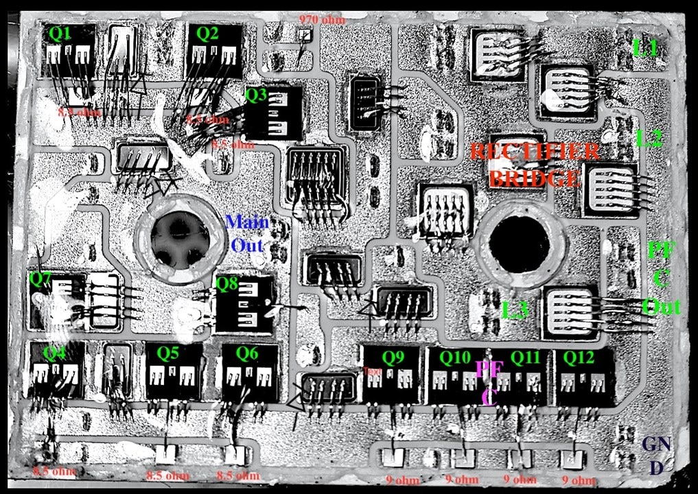
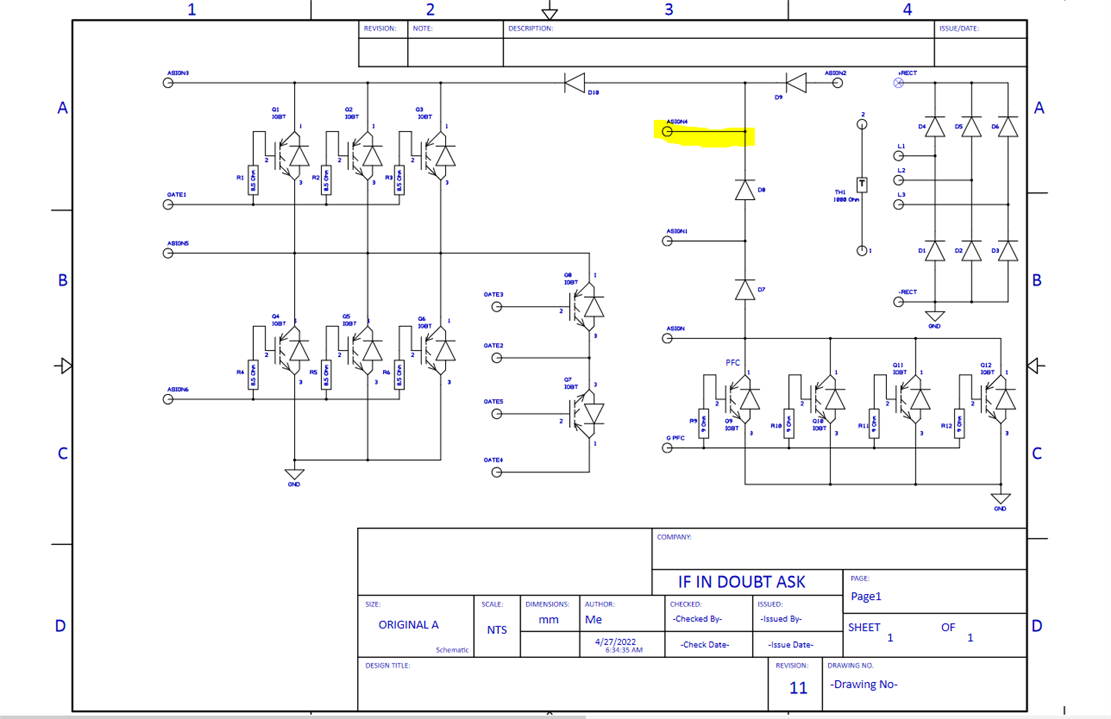
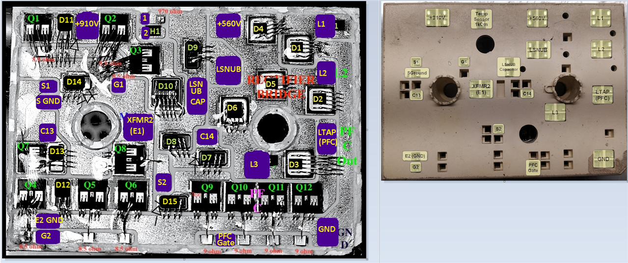
This is a restoration project attempt of reproducing using discreet components an obsolete  power module  which SkiiP 33NEC125T2 no longer produced by SEMIKRON.

DISCLAIMER: This is a high voltage project DANGER. Anyone who joins this experimental project need to be aware of high voltage (up to 1000v) and high currents (up to 100A) which is a high risk and requires to be qualified to work with such circuits and can be done only at your own risk.

  • Sign in to reply
  • Cancel

Top Replies

  • lanuser
    lanuser over 3 years ago in reply to mb443 +1
    I am no longer interested working on this project. Seems to me besides two people nobody else step forward. I have specially missed one pin on Schematic design, after I ask you to double check my work…
  • alvideo
    alvideo over 3 years ago in reply to alvideo +1
    I redraw module inside wiring like original, exept i added for all IGBT gate resistors. In wiring connectors names are like in module picture (see below). ` Here some more wiring outside…
Parents
  • lanuser
    lanuser over 3 years ago

    I do not take credit for someone else's work.

    Here is the assumed topology of the OEM diagram:

    image

    I am doing in this order:

    Separate Diode Power Bridge Rectifiers from IGBT components to reduce a heat spread.

    image

    OEM PART IMAGES:

    image image

    Now side by side:

    imageimage

    Here is someone else's work so I do NOT take credit for reverse engineering ( also this all just assumption based on this diagram )

    image

    Based on the diagram on the image following components is no longer available for sale:

    Component released on : July 2007

    And last but not leased another member of this forum made a PCB preview ( PCB not complete and needs redesign )

    image

    • Cancel
    • Vote Up 0 Vote Down
    • Sign in to reply
    • Cancel
  • mb443
    mb443 over 3 years ago in reply to lanuser

    it seems the bottom right corner of the original has 4 IGBTs in parallel which are used for PFC, not really critical if higher amps IGBTs used.

    Another thing is I will attempt to measure the threshold value of Vge for main IGBTs. Will publish when I'm done, so we can compare with FGL40N120 on schema above.

    • Cancel
    • Vote Up 0 Vote Down
    • Sign in to reply
    • Cancel
  • alvideo
    alvideo over 3 years ago in reply to lanuser

    What is Your site? 

    • Cancel
    • Vote Up 0 Vote Down
    • Sign in to reply
    • Cancel
  • lanuser
    lanuser over 3 years ago in reply to alvideo

    I stopped working on this project.

    Website: www.369support.com/1/

    However,  Site is closed to public... personal/internal  use only.

    If you need help let me know.

    Thank you.

    • Cancel
    • Vote Up 0 Vote Down
    • Sign in to reply
    • Cancel
  • serg200010
    serg200010 over 3 years ago in reply to lanuser

    Hello, I am interested with your project,  how i can register at your website?

    • Cancel
    • Vote Up 0 Vote Down
    • Sign in to reply
    • Cancel
  • alvideo
    alvideo over 3 years ago in reply to lanuser

    i have Miller DX200 powermodule main points waveforms (oscillograms). Maybe it change Your mind to continue this project? 

    • Cancel
    • Vote Up 0 Vote Down
    • Sign in to reply
    • Cancel
  • serg200010
    serg200010 over 3 years ago in reply to alvideo

    it will be Great! you you mind to share waveforms?  Thank you!

    • Cancel
    • Vote Up 0 Vote Down
    • Sign in to reply
    • Cancel
  • mb443
    mb443 over 3 years ago in reply to alvideo

    Hi alvideo, welcome back! I figured you'll continue with this. That's great! Did you actually succeed w/ testing? See if you want to drop interesting materials here, may really help others. Seems the army of dead units owners growing...

    • Cancel
    • Vote Up 0 Vote Down
    • Sign in to reply
    • Cancel
  • lanuser
    lanuser over 3 years ago in reply to serg200010

    Sorry my site for my personal use only.

    If you would like we can continue to work on this project here in this forum / board.

    However, I would like to see other members step into this project and share their finds and test results.

    If someone is interested I can repost Power Module images of reverse engineered info with "mb443" and i.

    • Cancel
    • Vote Up 0 Vote Down
    • Sign in to reply
    • Cancel
  • lanuser
    lanuser over 3 years ago in reply to lanuser

    imageimage

    imageimage

    imageimageimageimage

    • Cancel
    • Vote Up 0 Vote Down
    • Sign in to reply
    • Cancel
  • lanuser
    lanuser over 3 years ago in reply to serg200010

    image

    image

    • Cancel
    • Vote Up 0 Vote Down
    • Sign in to reply
    • Cancel
  • alvideo
    alvideo over 3 years ago in reply to lanuser

    All waveforms are taken in MMA mode, No LOAD (few years ago from working and tested Dynasty 200 welder).  

    Waveforms test points named as in service manual documentation (Page 70-71) 

    https://elektrotanya.com/miller_dynasty_200sd_dx_technical-manual.pdf/download.html

    01 RC4 1-2 Drive IGBT Gate 28 kHz

    RC4 1-2 Drive IGBT Gate 28 kHz

    02 Main TRANSFORMER XFMR1-XFMR2

    image

    03 RC1 4-3 Boost control (PFC) IGBT Gate 20kHz

    image

    04 PFC Choke LINPUT-LTAP

    image

    05 RC4 5-6 Snubber IGBT Gate 28kHz

    image

    06 LTAP-LSNUB

    image

    07 RC2 4-6 BuckDrive

    image

    • Cancel
    • Vote Up 0 Vote Down
    • Sign in to reply
    • Cancel
Reply
  • alvideo
    alvideo over 3 years ago in reply to lanuser

    All waveforms are taken in MMA mode, No LOAD (few years ago from working and tested Dynasty 200 welder).  

    Waveforms test points named as in service manual documentation (Page 70-71) 

    https://elektrotanya.com/miller_dynasty_200sd_dx_technical-manual.pdf/download.html

    01 RC4 1-2 Drive IGBT Gate 28 kHz

    RC4 1-2 Drive IGBT Gate 28 kHz

    02 Main TRANSFORMER XFMR1-XFMR2

    image

    03 RC1 4-3 Boost control (PFC) IGBT Gate 20kHz

    image

    04 PFC Choke LINPUT-LTAP

    image

    05 RC4 5-6 Snubber IGBT Gate 28kHz

    image

    06 LTAP-LSNUB

    image

    07 RC2 4-6 BuckDrive

    image

    • Cancel
    • Vote Up 0 Vote Down
    • Sign in to reply
    • Cancel
Children
  • alvideo
    alvideo over 3 years ago in reply to alvideo

    I redraw module inside wiring like original, exept i added for all IGBT gate resistors.   

    In wiring connectors names are like in module picture (see below).   


    image`

    image

    Here some more wiring outside module to understanding topology

    image

    • Cancel
    • Vote Up +1 Vote Down
    • Sign in to reply
    • Cancel
  • lanuser
    lanuser over 3 years ago in reply to alvideo

    Thank you for sharing information !!!

    Can I ask for detailed information for Gate Voltage Drives? I would need to pick proper Zenner Diode to avoid voltage jump for unrealizable power source.  

    Also keep in mind per your schematic above: Q3 & Q4  also should have 6-9Ohm to gate & should not have floating Gate.

    • Cancel
    • Vote Up 0 Vote Down
    • Sign in to reply
    • Cancel
  • serg200010
    serg200010 over 3 years ago in reply to alvideo

    Thank you so much for sharing info.

    I have to welder, Miller Maxstar 200 LX and Miller Maxstar 200 SD. LX has a problem with discrete elements, I will share photos of my board and what I fixed, SD has a broken IGBT ( Q4 is shorted , I have cut the wires connected to it, haven't check it yet, waiting for components) 

    • Cancel
    • Vote Up 0 Vote Down
    • Sign in to reply
    • Cancel
  • alvideo
    alvideo over 3 years ago in reply to lanuser

    This is module wiring, exept added resistors and two zener diodes. Also in wiring missing 3 ph bridge rectifier. In welder is a lot of space to mount serparate bridge on radiator like this 

    image

    Need more wiring modifications or add/remove components?  Any suggestions?

    If not, time to choose correct and specific ALL IGBT and diodes D1-D4.    

    image

    • Cancel
    • Vote Up 0 Vote Down
    • Sign in to reply
    • Cancel
  • lanuser
    lanuser over 3 years ago in reply to alvideo

    Do you have your Brocken / Damaged Module on hand?

    • Cancel
    • Vote Up 0 Vote Down
    • Sign in to reply
    • Cancel
  • serg200010
    serg200010 over 3 years ago in reply to lanuser

    Yes i do

    • Cancel
    • Vote Up 0 Vote Down
    • Sign in to reply
    • Cancel
  • lanuser
    lanuser over 3 years ago in reply to alvideo

    IMO, Zenner's should be on all IGBT gates. Also R4 R6 10k 

    • Cancel
    • Vote Up 0 Vote Down
    • Sign in to reply
    • Cancel
  • lanuser
    lanuser over 3 years ago in reply to serg200010

    Excellent!

    With your approval will be interested to isolate damaged part in Power Module and replaced with external components.

    Also will be nice, If someone has discord channel. 

    • Cancel
    • Vote Up 0 Vote Down
    • Sign in to reply
    • Cancel
  • serg200010
    serg200010 over 3 years ago in reply to lanuser

    I have enough K25H120J (30pcs),may be we can use it

    • Cancel
    • Vote Up 0 Vote Down
    • Sign in to reply
    • Cancel
  • serg200010
    serg200010 over 3 years ago in reply to serg200010

    K25H1203 - 30pcs

    • Cancel
    • Vote Up 0 Vote Down
    • Sign in to reply
    • Cancel
element14 Community

element14 is the first online community specifically for engineers. Connect with your peers and get expert answers to your questions.

  • Members
  • Learn
  • Technologies
  • Challenges & Projects
  • Products
  • Store
  • About Us
  • Feedback & Support
  • FAQs
  • Terms of Use
  • Privacy Policy
  • Legal and Copyright Notices
  • Sitemap
  • Cookies

An Avnet Company © 2025 Premier Farnell Limited. All Rights Reserved.

Premier Farnell Ltd, registered in England and Wales (no 00876412), registered office: Farnell House, Forge Lane, Leeds LS12 2NE.

ICP 备案号 10220084.

Follow element14

  • X
  • Facebook
  • linkedin
  • YouTube