How to determine the type of resistor to be used when connecting a transistor
Be sure to click 'more' and select 'suggest as answer'!
If you're the thread creator, be sure to click 'more' then 'Verify as Answer'!
How to determine the type of resistor to be used when connecting a transistor
You will need to provide a lot more information to get a sensible answer.
What are you trying to do ?
To know the actual value of resistor for construction of a transistor as to prevent it from burning out by a high current or voltage
That would depend on the transistor, the load, the application and a whole load more things.
When I said explain what you are trying to do I meant like:
turning an LED on and off
controling a room heater
Transistors come in thousands of different types , capable of handling currents from a few nA to a few thousand amps - to calculate the compoents in a circuit then first you need to knwo what it supposed to do.
MK
Turning on and off an LED
The transistor am using is NPN
I need the formula of getting it right, how to know for instance that either 1 kilo ohm resistor is to be used

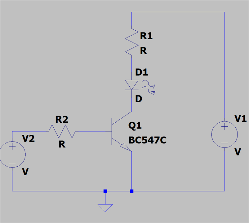
1 Decide the current you want in the LED (check the data sheet) call it Iled
2 Choose the power supply voltage V1
3 Choose the control voltage to switch the transistor on, V2
4 If the transistor is suitable and switched on the voltage on its collector will be low so the voltage across R1 and D1 will be V1
5 Look up the forward voltage of the LED (Vled) in the data sheet
6 The current through R1 will be (V1 - Vled)/R1, so Iled = (V1 - Vled)/R1
7 R1 = (V1 - Vled)/Iled
8 if V1 = 5V, Iled = 10mA, Vled = 1.2V then R1 = (5 - 1.1)/0.01 = 390R
10 For the transistor to be really well turned on the base current should be at least collector current/25
11 In our example base current = 10mA/25 = 0.4mA
12 So R2 = (V2 -0.6)/0.4mA
13 if V2 = 5V then R2 = 11k
When you build this, please send a picture so we can see it working, it's no fun answering questions if you don't get feedback !
MK
There will be a few variables. I am assuming an NPN setup where there is a resistor in series with LED between V+ and collector. Emitter to ground. And the base used to switch (edit: michaelkellett's schematic above).
Step 1: output side
you need to know
Then you can calculate the resistor:
Now you know how to dimension the resistor, because:
Don't look for a resistor with the exact value. This isn't high precision electronics. Look for the cheapest one that's close to this.
If you're at the upper range of the LED current, then use a resistor greater than the calculated value. To avoid exceeding the LEDs limits.
Then, you can calculate how hard you need to drive the basis to get the transistor saturated at 12 mA ...
edit : that is step 10 in michaelkellett's reply above