element14 Community
element14 Community
    Register Log In
  • Site
  • Search
  • Log In Register
  • About Us
  • Community Hub
    Community Hub
    • What's New on element14
    • Feedback and Support
    • Benefits of Membership
    • Personal Blogs
    • Members Area
    • Achievement Levels
  • Learn
    Learn
    • Ask an Expert
    • eBooks
    • element14 presents
    • Learning Center
    • Tech Spotlight
    • STEM Academy
    • Webinars, Training and Events
    • Learning Groups
  • Technologies
    Technologies
    • 3D Printing
    • FPGA
    • Industrial Automation
    • Internet of Things
    • Power & Energy
    • Sensors
    • Technology Groups
  • Challenges & Projects
    Challenges & Projects
    • Design Challenges
    • element14 presents Projects
    • Project14
    • Arduino Projects
    • Raspberry Pi Projects
    • Project Groups
  • Products
    Products
    • Arduino
    • Avnet Boards Community
    • Dev Tools
    • Manufacturers
    • Multicomp Pro
    • Product Groups
    • Raspberry Pi
    • RoadTests & Reviews
  • Store
    Store
    • Visit Your Store
    • Choose another store...
      • Europe
      •  Austria (German)
      •  Belgium (Dutch, French)
      •  Bulgaria (Bulgarian)
      •  Czech Republic (Czech)
      •  Denmark (Danish)
      •  Estonia (Estonian)
      •  Finland (Finnish)
      •  France (French)
      •  Germany (German)
      •  Hungary (Hungarian)
      •  Ireland
      •  Israel
      •  Italy (Italian)
      •  Latvia (Latvian)
      •  
      •  Lithuania (Lithuanian)
      •  Netherlands (Dutch)
      •  Norway (Norwegian)
      •  Poland (Polish)
      •  Portugal (Portuguese)
      •  Romania (Romanian)
      •  Russia (Russian)
      •  Slovakia (Slovak)
      •  Slovenia (Slovenian)
      •  Spain (Spanish)
      •  Sweden (Swedish)
      •  Switzerland(German, French)
      •  Turkey (Turkish)
      •  United Kingdom
      • Asia Pacific
      •  Australia
      •  China
      •  Hong Kong
      •  India
      •  Korea (Korean)
      •  Malaysia
      •  New Zealand
      •  Philippines
      •  Singapore
      •  Taiwan
      •  Thailand (Thai)
      • Americas
      •  Brazil (Portuguese)
      •  Canada
      •  Mexico (Spanish)
      •  United States
      Can't find the country/region you're looking for? Visit our export site or find a local distributor.
  • Translate
  • Profile
  • Settings
Experts, Learning and Guidance
  • Technologies
  • More
Experts, Learning and Guidance
Ask an Expert Forum How it this analog front end circuit working?
  • Blog
  • Forum
  • Documents
  • Leaderboard
  • Files
  • Members
  • Mentions
  • Sub-Groups
  • Tags
  • More
  • Cancel
  • New
Join Experts, Learning and Guidance to participate - click to join for free!
Actions
  • Share
  • More
  • Cancel
Forum Thread Details
  • Replies 13 replies
  • Subscribers 281 subscribers
  • Views 3789 views
  • Users 0 members are here
  • analog
Related
See a helpful answer?

Be sure to click 'more' and select 'suggest as answer'!

If you're the thread creator, be sure to click 'more' then 'Verify as Answer'!

How it this analog front end circuit working?

Sudeep AJ
Sudeep AJ over 2 years ago

image

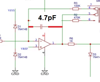
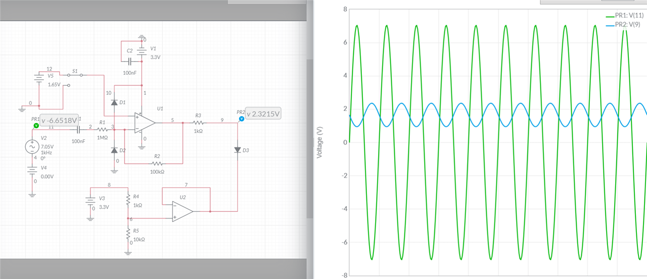
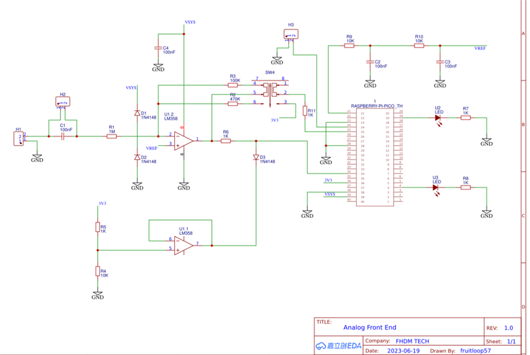
This circuit has been taken from a "DIY Oscilloscope" project. This circuit is changing the input wave swing to 0V to 3.3V. The circled voltage source is Vsys/2, which is the voltage at which the zero level of the input wave will be shifted to. Vsys is 3.3V here. 

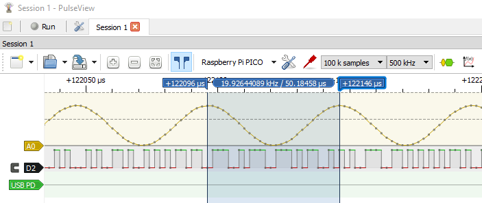
The output is as follows:

image

I wanted to know how is this working and can I use it for my project?

The original circuit with Raspberry PI PICO is as follows.

image

Thank you.

  • Sign in to reply
  • Cancel

Top Replies

  • wolfgangfriedrich
    wolfgangfriedrich over 2 years ago +5
    U1 is set up as inverting opamp with gain of -R2/R1 = -0.1 and biased to the voltage on the positiv input 1.65 V (= 3.3V/2) because of the AC coupling cap C1. So the input sin wave with 14.1 V peak to…
  • scottiebabe
    scottiebabe over 2 years ago +4
    Its not the best circuit ever but its definitely worth putting on a breadboard and experimenting with it. With these magnitude of resistors in the feedback path you may find you need a tiny compensation…
  • phoenixcomm
    phoenixcomm over 2 years ago +3
    Sudeep AJ Ok, here we go. I hate to do this but, did you figure out what bandwidth you need? I noticed that you limit your voltage to 3.3v which by the way is a FLOATER in TTL. I personally think you are…
  • wolfgangfriedrich
    wolfgangfriedrich over 2 years ago

    U1 is set up as inverting opamp with gain of -R2/R1 = -0.1 and biased to the voltage on the positiv input 1.65 V (= 3.3V/2) because of the AC coupling cap C1. So the input sin wave with 14.1 V peak to peak will be transformed to a 'negative' sin wave 1.41V peak to peak centered around 1.65 V or 1.65 V +- 0.705 V

    This circuit with the LM358 and powered from 3.3V will only work for very small signals (peak to peak 1.8 V), because of the input voltage range is only (V+)  - 1.5 V =  1.8 V. You need a rail to rail opamp for this application. 

    • Cancel
    • Vote Up +5 Vote Down
    • Sign in to reply
    • Cancel
  • dougw
    dougw over 2 years ago

     As wolfgangfriedrich indicates, this circuit attenuates the input by a factor of 10, but it would work over a wider range of input voltages if it used rail-to-rail output opamps.

    U1-1 might be problematic as a clamping circuit with this particular op-amp, but it can't exceed the rail unless VSYS is a high voltage, so it shouldn't even be needed in this circuit.

    • Cancel
    • Vote Up +2 Vote Down
    • Sign in to reply
    • Cancel
  • phoenixcomm
    phoenixcomm over 2 years ago

     Sudeep AJ  Ok, here we go. I hate to do this but, did you figure out what bandwidth you need? I noticed that you limit your voltage to 3.3v which by the way is a FLOATER in TTL. I personally think you are going to have a toy when you're done.image 
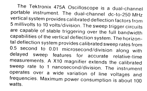
Save the sweat, money, and time and pick up a good used scope. You can pick one up like my old Tektronix 475A for about 150 bucks plus shipping. I have inserted the first

    a paragraph from the manual.  image

    Please note that I can see 1ns/div which I do use when I have noise transits from things like Switches, Keyboards, and Relays. In other words any contactor. 

    If you go through this exercise remember that the front end is ANALOG and therefore near RF frequencies, and EVERYTHING MUST BE SHIELDED. Also, my probes (Tektronix) have a built-in compensator as well as a 10:1 divider, and they're good to 500 MHz. 

    Please enjoy the project just keep some of my wisdom in your mind. ~~ CAH

    • Cancel
    • Vote Up +3 Vote Down
    • Sign in to reply
    • Cancel
  • Sudeep AJ
    Sudeep AJ over 2 years ago in reply to dougw

    wolfgangfriedrich  dougw . Thank you for your valuable inputs. If I really need rail-to-rail op-amp and input range is only 1.8V. How in simulation it is working then? In simulation it seems like it is serving the purpose, basically taking the input sine of large swing to 0V - 3.3V swing centered around 1.65V so that my Microcontroller can take it properly. What I also observed in the simulation is, if I change the Vsys to 5V(if I want to connect it to Arduino UNO) and make the reference voltage as 2.5V, it serves the purpose too. I am also not understanding the purpose the U2 op-amp and 3 Diodes.

    • Cancel
    • Vote Up 0 Vote Down
    • Sign in to reply
    • Cancel
  • ggabe
    ggabe over 2 years ago in reply to Sudeep AJ

    All 3 diodes are clamping voltages to protect the opamp input from over voltage as well as the MCU. The value of D3 and its opamp buffer, U1:1 is questionable, if the opamp is on a 3.3V rail and the MCU input can go up to 3.3V.

    I agree the LM358 is a bad choice, primarily b/c the low bandwidth and the non linearity it has in the crossover region. The input voltage range is not limited by the output swing, and the inverting input always maintains 1/2Vcc. It would be nice to use the full range up to full Vcc, however this benefit comes if the MCU’s ADC input tolerates up to full Vcc. Not all does. 

    • Cancel
    • Vote Up +3 Vote Down
    • Sign in to reply
    • Cancel
  • scottiebabe
    scottiebabe over 2 years ago

    Its not the best circuit ever but its definitely worth putting on a breadboard and experimenting with it.

    With these magnitude of resistors in the feedback path you may find you need a tiny compensation capacitor for stability

    image

    On a breadboard you could just twist 2 insulated wire together to make your own, if need be.

    • Cancel
    • Vote Up +4 Vote Down
    • Sign in to reply
    • Cancel
  • scottiebabe
    scottiebabe over 2 years ago in reply to scottiebabe

    Vsys on the PICO is VUSB minus the voltage drop of a Schottky diode, which leaves an LM358 enough headroom to output 3.3V.

    • Cancel
    • Vote Up +1 Vote Down
    • Sign in to reply
    • Cancel
  • Sudeep AJ
    Sudeep AJ over 2 years ago in reply to scottiebabe

    Thank you for your inputs!

    • Cancel
    • Vote Up +1 Vote Down
    • Sign in to reply
    • Cancel
  • Sudeep AJ
    Sudeep AJ over 2 years ago in reply to ggabe

    thank you for your inputs! If LM358 is a bad choice which one do you prefer?  And I am not understanding the notation U1:1 / U1-1, What does that mean??

    • Cancel
    • Vote Up 0 Vote Down
    • Sign in to reply
    • Cancel
  • scottiebabe
    scottiebabe over 2 years ago in reply to Sudeep AJ

    You're Welcome. I have tried the pico with pulseview

    https://github.com/pico-coder/sigrok-pico 

    FNB58 USB Power Tester - element14 Community

    I will have to try the Scoppy project you linked to in the future, thanks for sharing!

    • Cancel
    • Vote Up +1 Vote Down
    • Sign in to reply
    • Cancel
>
element14 Community

element14 is the first online community specifically for engineers. Connect with your peers and get expert answers to your questions.

  • Members
  • Learn
  • Technologies
  • Challenges & Projects
  • Products
  • Store
  • About Us
  • Feedback & Support
  • FAQs
  • Terms of Use
  • Privacy Policy
  • Legal and Copyright Notices
  • Sitemap
  • Cookies

An Avnet Company © 2025 Premier Farnell Limited. All Rights Reserved.

Premier Farnell Ltd, registered in England and Wales (no 00876412), registered office: Farnell House, Forge Lane, Leeds LS12 2NE.

ICP 备案号 10220084.

Follow element14

  • X
  • Facebook
  • linkedin
  • YouTube