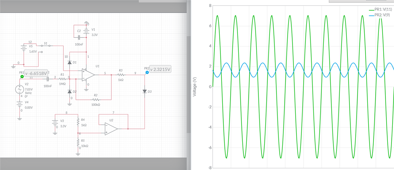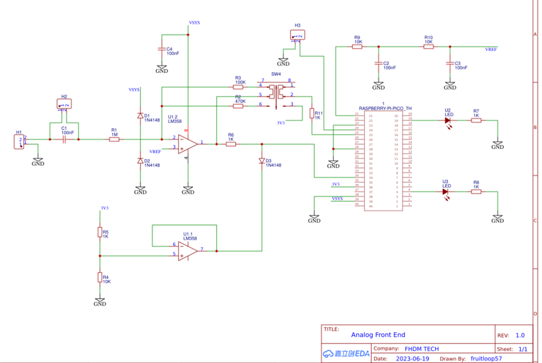
This circuit has been taken from a "DIY Oscilloscope" project. This circuit is changing the input wave swing to 0V to 3.3V. The circled voltage source is Vsys/2, which is the voltage at which the zero level of the input wave will be shifted to. Vsys is 3.3V here.
The output is as follows:

I wanted to know how is this working and can I use it for my project?
The original circuit with Raspberry PI PICO is as follows.

Thank you.
