Morning all
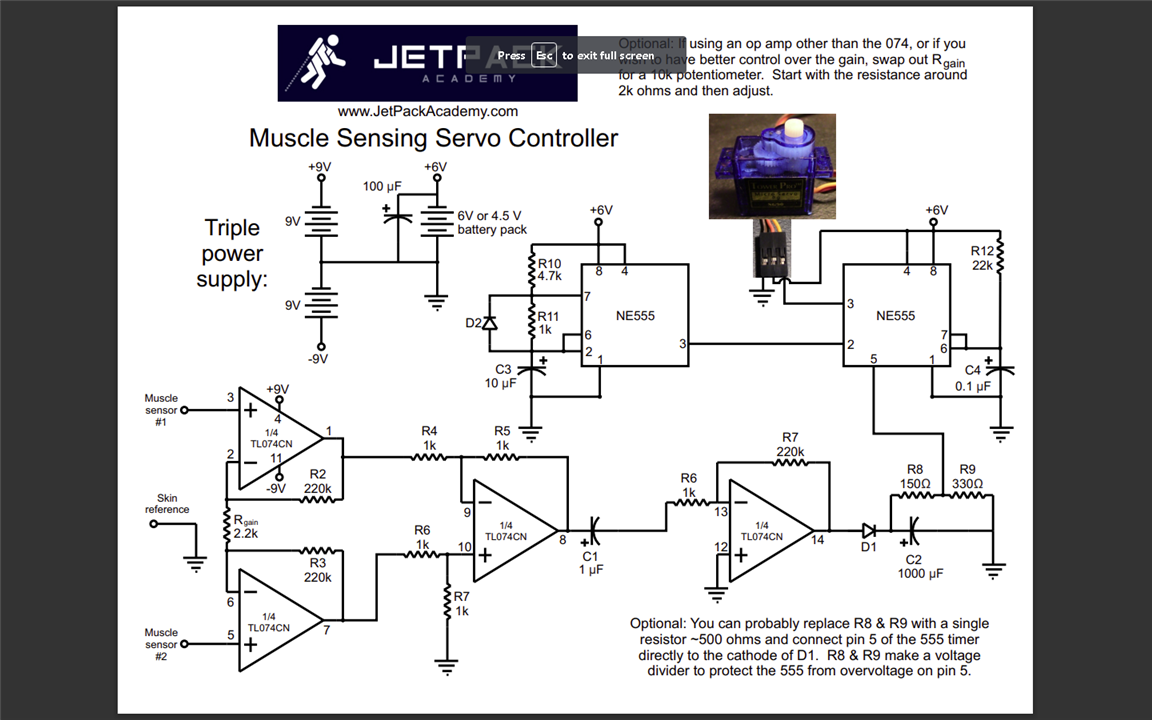
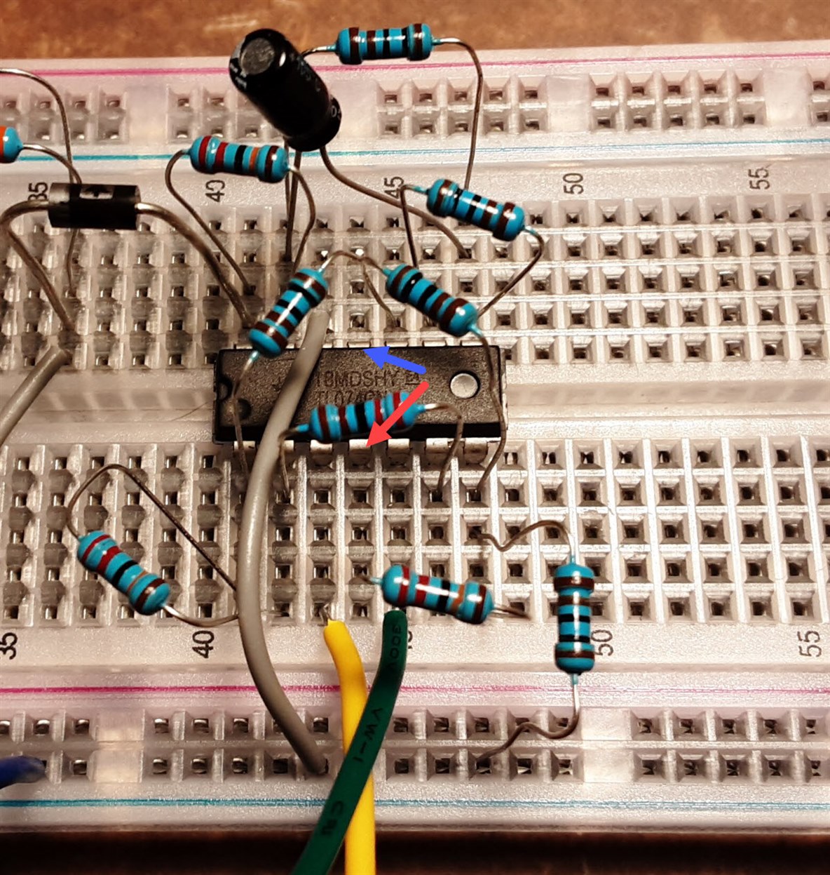
So i started a Udemy class on Electronics and Robotics a while ago, and frankly I'm struggling. Apparently I'm great at building circuits from a photo or a video, but I have a lot of issues with schematics. Not super relevant to the post, but it may be helpful to you all to know where I'm coming from. I hope this isn't offside, but if some fine peeps could take a look at what I've built, see if I missed anything, or miss placed anything, that would be super helpful. Normally id just harass the instructor, but the class is 7 years old, and he is busy with other projects now and doesn't get back to me very often.
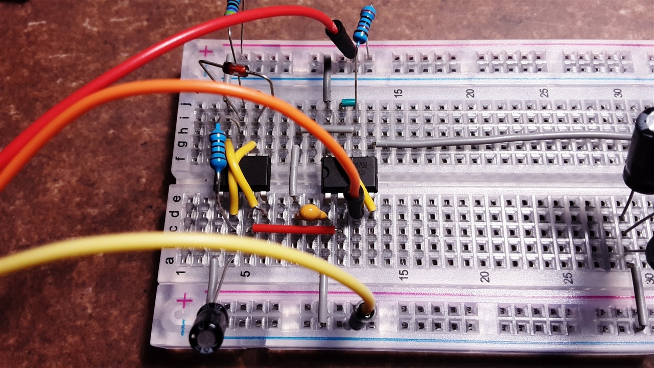
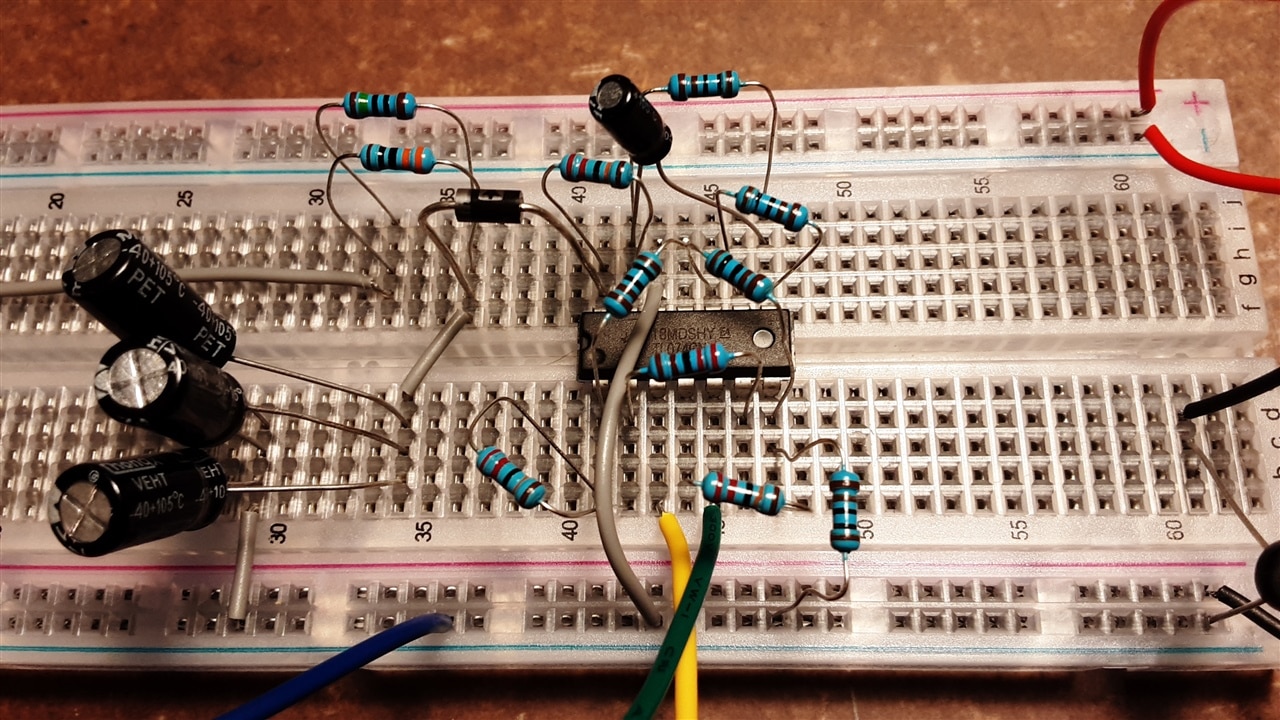
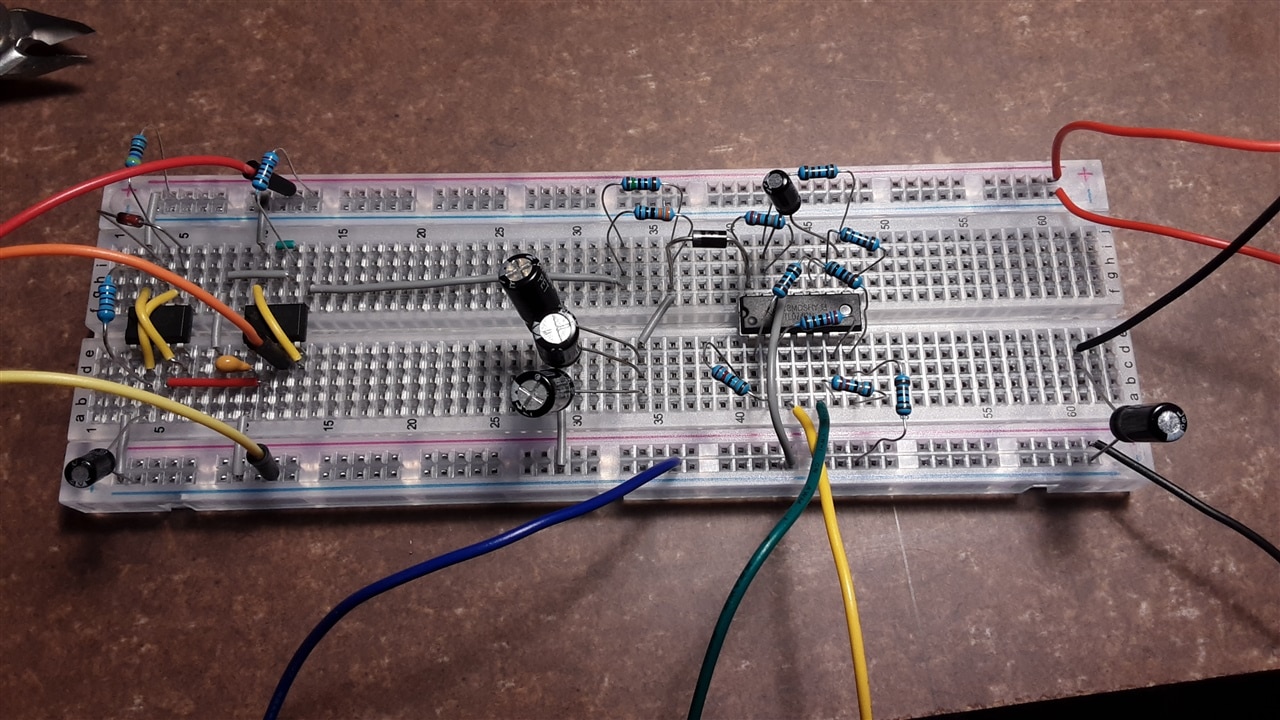
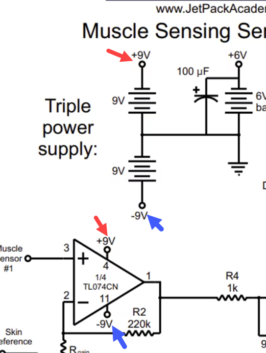
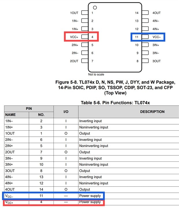
So, red, orange and yellow wires on the left go to the micro servo. Blue, green and yellow at bottom right go to the muscle sensors. Top positive and bottom negative are 6v, and the neg is also my ground (unsure about that, prof kinda skimmed that detail). Top negative is positive 9v, and bottom positive is neg 9v. Did that just to keep things straight in my head. I didn't have a 1000 cap, hence the stack of 3 in the middle of the board.
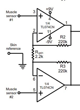
Main concern i have, that it dosnt work. Beyond that, from going through the class forum from many years ago, other students had a sh*t load of wires coming off the amp. I get that we all build differently, but just have 2, not 30. Maybe more weird than concerning.
Again, any insights are helpful.

 (Image source: