element14 Community
element14 Community
    Register Log In
  • Site
  • Search
  • Log In Register
  • Community Hub
    Community Hub
    • What's New on element14
    • Feedback and Support
    • Benefits of Membership
    • Personal Blogs
    • Members Area
    • Achievement Levels
  • Learn
    Learn
    • Ask an Expert
    • eBooks
    • element14 presents
    • Learning Center
    • Tech Spotlight
    • STEM Academy
    • Webinars, Training and Events
    • Learning Groups
  • Technologies
    Technologies
    • 3D Printing
    • FPGA
    • Industrial Automation
    • Internet of Things
    • Power & Energy
    • Sensors
    • Technology Groups
  • Challenges & Projects
    Challenges & Projects
    • Design Challenges
    • element14 presents Projects
    • Project14
    • Arduino Projects
    • Raspberry Pi Projects
    • Project Groups
  • Products
    Products
    • Arduino
    • Avnet & Tria Boards Community
    • Dev Tools
    • Manufacturers
    • Multicomp Pro
    • Product Groups
    • Raspberry Pi
    • RoadTests & Reviews
  • About Us
  • Store
    Store
    • Visit Your Store
    • Choose another store...
      • Europe
      •  Austria (German)
      •  Belgium (Dutch, French)
      •  Bulgaria (Bulgarian)
      •  Czech Republic (Czech)
      •  Denmark (Danish)
      •  Estonia (Estonian)
      •  Finland (Finnish)
      •  France (French)
      •  Germany (German)
      •  Hungary (Hungarian)
      •  Ireland
      •  Israel
      •  Italy (Italian)
      •  Latvia (Latvian)
      •  
      •  Lithuania (Lithuanian)
      •  Netherlands (Dutch)
      •  Norway (Norwegian)
      •  Poland (Polish)
      •  Portugal (Portuguese)
      •  Romania (Romanian)
      •  Russia (Russian)
      •  Slovakia (Slovak)
      •  Slovenia (Slovenian)
      •  Spain (Spanish)
      •  Sweden (Swedish)
      •  Switzerland(German, French)
      •  Turkey (Turkish)
      •  United Kingdom
      • Asia Pacific
      •  Australia
      •  China
      •  Hong Kong
      •  India
      •  Korea (Korean)
      •  Malaysia
      •  New Zealand
      •  Philippines
      •  Singapore
      •  Taiwan
      •  Thailand (Thai)
      • Americas
      •  Brazil (Portuguese)
      •  Canada
      •  Mexico (Spanish)
      •  United States
      Can't find the country/region you're looking for? Visit our export site or find a local distributor.
  • Translate
  • Profile
  • Settings
Experts, Learning and Guidance
  • Technologies
  • More
Experts, Learning and Guidance
Ask an Expert Forum Muscle to micro servo circuit
  • Blog
  • Forum
  • Documents
  • Leaderboard
  • Files
  • Members
  • Mentions
  • Sub-Groups
  • Tags
  • More
  • Cancel
  • New
Join Experts, Learning and Guidance to participate - click to join for free!
Actions
  • Share
  • More
  • Cancel
Forum Thread Details
  • Replies 40 replies
  • Subscribers 295 subscribers
  • Views 4757 views
  • Users 0 members are here
Related
See a helpful answer?

Be sure to click 'more' and select 'suggest as answer'!

If you're the thread creator, be sure to click 'more' then 'Verify as Answer'!

Muscle to micro servo circuit

Doppleganger
Doppleganger over 2 years ago

Morning all

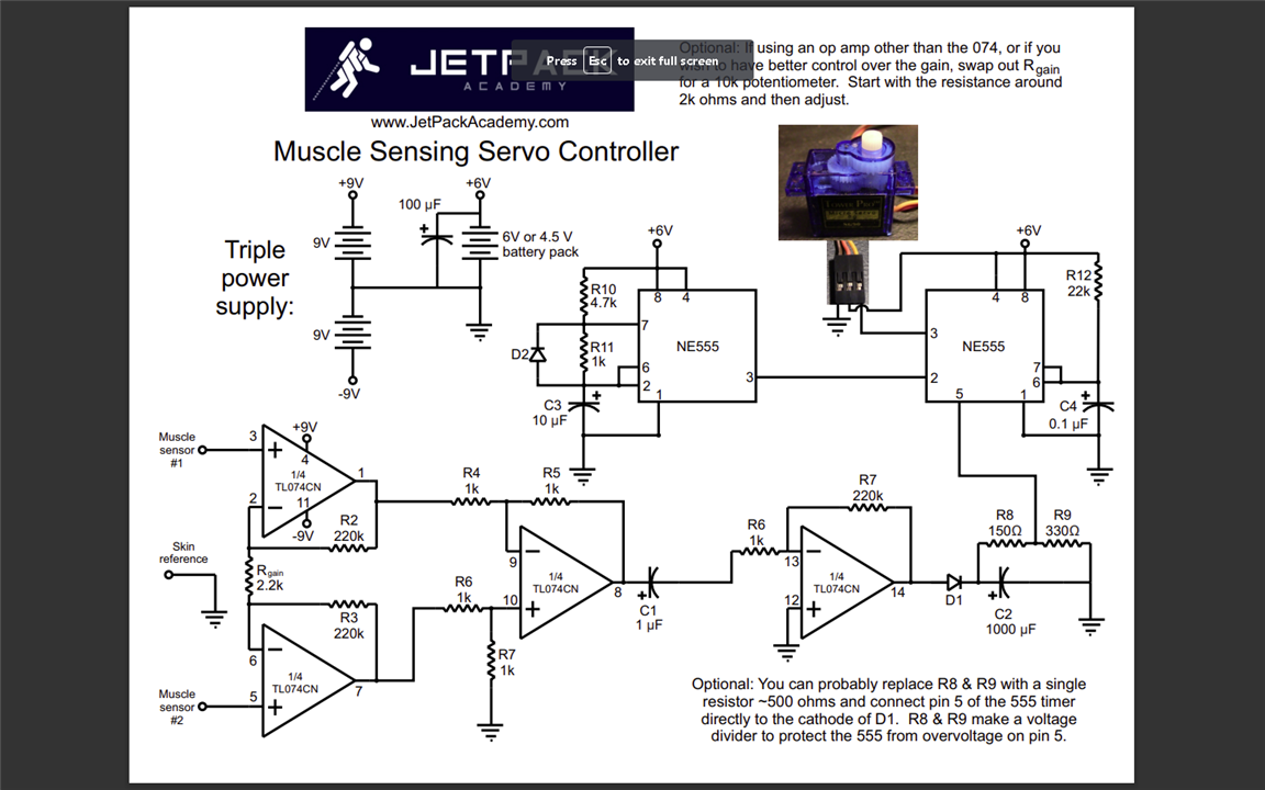
So i started a Udemy class on Electronics and Robotics a while ago, and frankly I'm struggling. Apparently I'm great at building circuits from a photo or a video, but I have a lot of issues with schematics. Not super relevant to the post, but it may be helpful to you all to know where I'm coming from. I hope this isn't offside, but if some fine peeps could take a look at what I've built, see if I missed anything, or miss placed anything, that would be super helpful. Normally id just harass the instructor, but the class is 7 years old, and he is busy with other projects now and doesn't get back to me very often. 

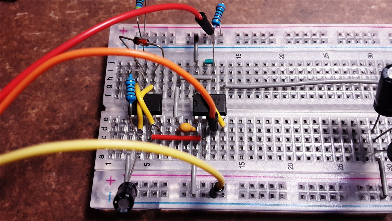
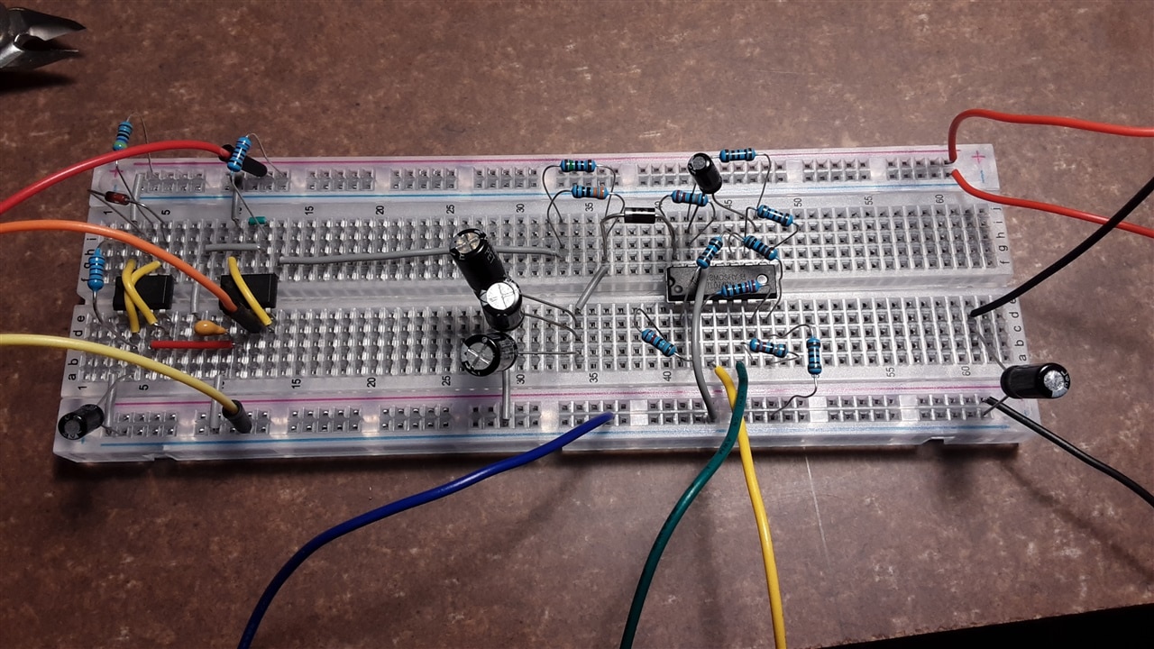
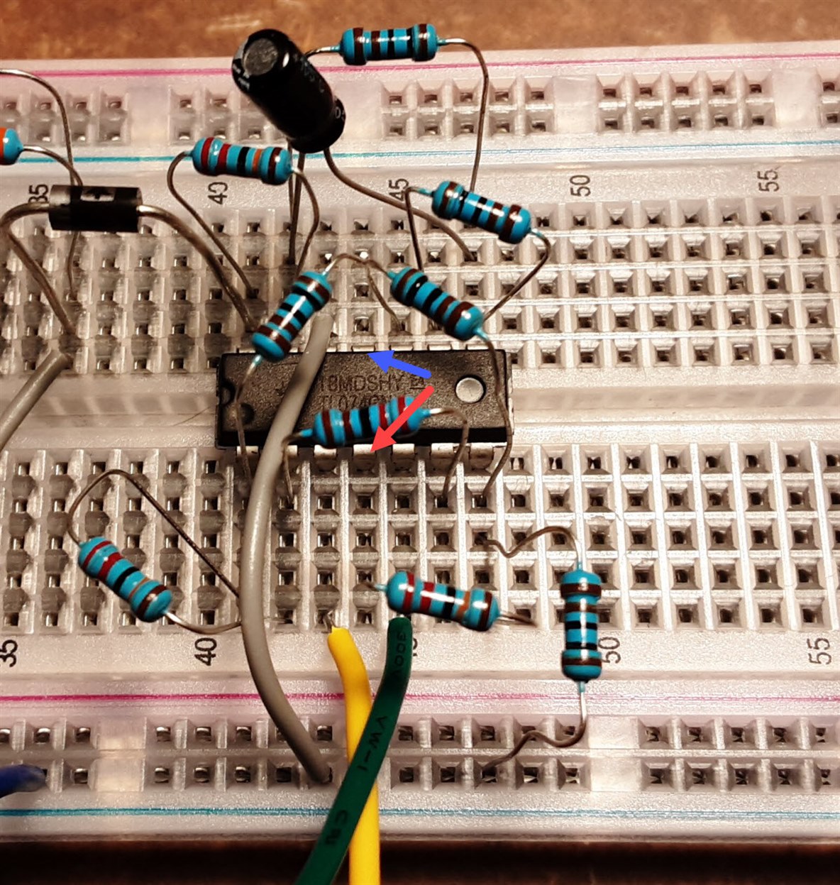
So, red, orange and yellow wires on the left go to the micro servo. Blue, green and yellow at bottom right go to the muscle sensors. Top positive and bottom negative are 6v, and the neg is also my ground (unsure about that, prof kinda skimmed that detail). Top negative is positive 9v, and bottom positive is neg 9v. Did that just to keep things straight in my head. I didn't have a 1000 cap, hence the stack of 3 in the middle of the board. 

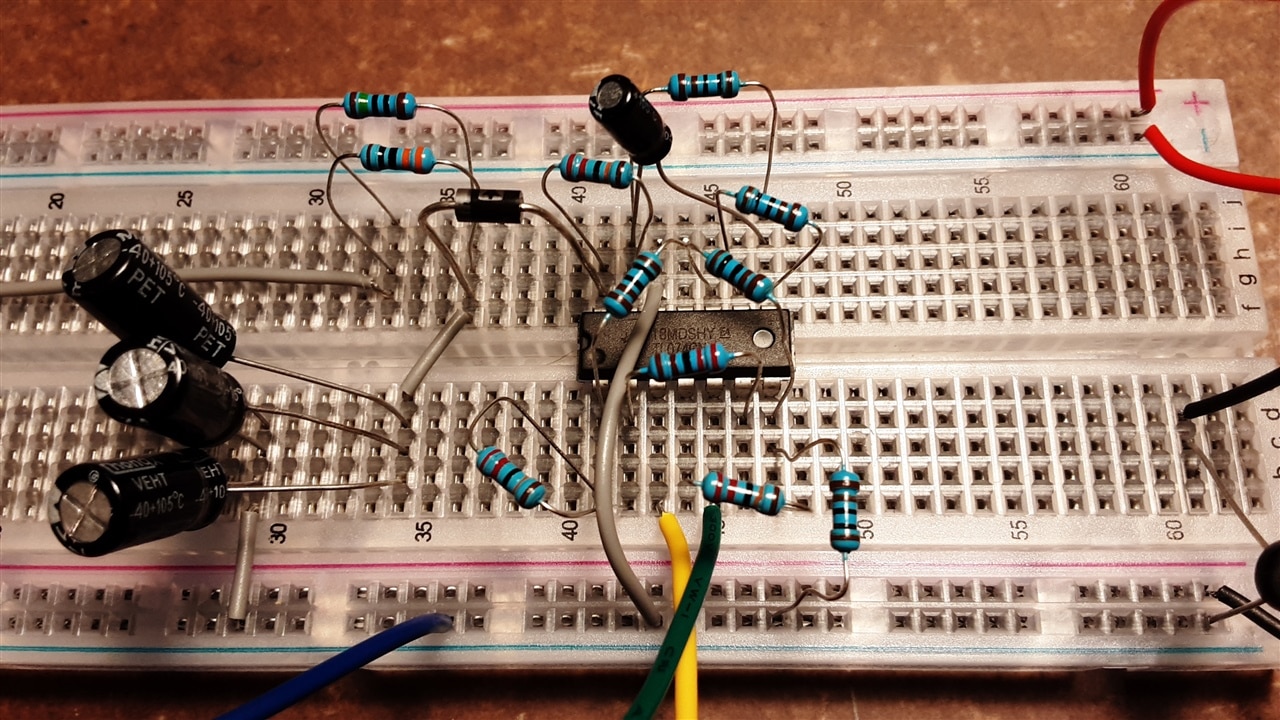
Main concern i have, that it dosnt work. Beyond that, from going through the class forum from many years ago, other students had a sh*t load of wires coming off the amp. I get that we all build differently, but just have 2, not 30. Maybe more weird than concerning.

Again, any insights are helpful.

imageimageimageimage

  • Sign in to reply
  • Cancel

Top Replies

  • shabaz
    shabaz over 2 years ago +5
    Hi, You don't seem to have wired up pins 4 and 11 of the TL074 chip.
  • rad_bcit
    rad_bcit over 2 years ago +4
    Hello, I teach breadboarding skills and my immediate reaction to your photos is to say that the easiest remedy to your wiring issues is to tidy up the way you do your breadboarding. I would ask you to…
  • michaelkellett
    michaelkellett over 2 years ago in reply to Doppleganger +4
    I looked through the replies you got and didn't find any at all with the phrases you quoted. It seemed quite a good response to me, you got a lot of good and relevant answers and the usual E14 diversions…
Parents
  • shabaz
    shabaz over 2 years ago

    Hi,

    You don't seem to have wired up pins 4 and 11 of the TL074 chip.

    image

    • Cancel
    • Vote Up +5 Vote Down
    • Sign in to reply
    • Cancel
  • Doppleganger
    Doppleganger over 2 years ago in reply to shabaz

    Thanks Shabaz, i dont see pins 4 or 11 on the schematic though. The pinout says 4 is Vcc and 11 is Vee, i vaguely remember the prof saying thats for voltage in and out, by my old man brain may be mis-remembering. And even that wouldnt make much sense as 6v and 9v are already conected at various points.  Priciate the reply.

    • Cancel
    • Vote Up 0 Vote Down
    • Sign in to reply
    • Cancel
  • genebren
    genebren over 2 years ago in reply to Doppleganger

    Pins 4 and 11 are in fact on the schematic.  They are the power pins to the Op-amps, shown connected to 9V and -9V.

    • Cancel
    • Vote Up +2 Vote Down
    • Sign in to reply
    • Cancel
  • genebren
    genebren over 2 years ago in reply to genebren

    image

    • Cancel
    • Vote Up +3 Vote Down
    • Sign in to reply
    • Cancel
  • shabaz
    shabaz over 2 years ago in reply to genebren

    Exactly as Gene says:

    image

    The chip needs a power source, and the TL074 datasheet can also be examined, it too will indicate this.

    • Cancel
    • Vote Up +2 Vote Down
    • Sign in to reply
    • Cancel
  • shabaz
    shabaz over 2 years ago in reply to genebren

    Sorry our replies crossed! : )

    • Cancel
    • Vote Up 0 Vote Down
    • Sign in to reply
    • Cancel
  • genebren
    genebren over 2 years ago in reply to shabaz

    No problem, I was just backing up what you found anyway.

    • Cancel
    • Vote Up 0 Vote Down
    • Sign in to reply
    • Cancel
  • Doppleganger
    Doppleganger over 2 years ago in reply to genebren

    Ballz. Thanks guys, i didnt even see that, i only saw the pin references on the outside of the "triangle". So then 6v runs the 555 timer chips and 9v for the 74 chip?

    • Cancel
    • Vote Up 0 Vote Down
    • Sign in to reply
    • Cancel
  • shabaz
    shabaz over 2 years ago in reply to Doppleganger

    The 6V is being used to power the servos and the 555. 

    The +9V and -9V supplies are being used for the TL074 quad op-amp.

    image (Image source: TL074 datasheet)

    • Cancel
    • Vote Up +1 Vote Down
    • Sign in to reply
    • Cancel
Reply
  • shabaz
    shabaz over 2 years ago in reply to Doppleganger

    The 6V is being used to power the servos and the 555. 

    The +9V and -9V supplies are being used for the TL074 quad op-amp.

    image (Image source: TL074 datasheet)

    • Cancel
    • Vote Up +1 Vote Down
    • Sign in to reply
    • Cancel
Children
No Data
element14 Community

element14 is the first online community specifically for engineers. Connect with your peers and get expert answers to your questions.

  • Members
  • Learn
  • Technologies
  • Challenges & Projects
  • Products
  • Store
  • About Us
  • Feedback & Support
  • FAQs
  • Terms of Use
  • Privacy Policy
  • Legal and Copyright Notices
  • Sitemap
  • Cookies

An Avnet Company © 2025 Premier Farnell Limited. All Rights Reserved.

Premier Farnell Ltd, registered in England and Wales (no 00876412), registered office: Farnell House, Forge Lane, Leeds LS12 2NE.

ICP 备案号 10220084.

Follow element14

  • X
  • Facebook
  • linkedin
  • YouTube