


Table of Contents
Introduction
For ages, I’ve wanted an easy-to-use flexible/configurable circuit that would send devices to sleep but wake them up when needed. Finally, I got around to it, and this project was the result.
This project can be used to automatically power up and shut down circuits, to conserve battery power.
By default, it will wake up every 30 seconds and then shut down again after 2 seconds. This might be useful for temperature logging for instance. The circuit will also automatically awake if a particular pin input is set high; it could be attached to a push-button for powering on the system for instance.
You can modify the behavior at any time, by using I2C. As an example, you can send an I2C command to change the wake-up rate to 5 minutes, or any other value.
There are also some extra features; I tried to squeeze in as many as practical, within the memory constraints of the microcontroller I’m using for this project.
The extra features are:
- 64 bytes of I2C-accessible battery-backed RAM for storing useful stuff
- General-purpose pins for input/output (GPIO), again I2C-accessible
- I2C-accessible real-time clock (RTC)
The project runs from a coin cell (CR2032) and it should last for several years of operation (average current consumption is under 1 uA).
Using It
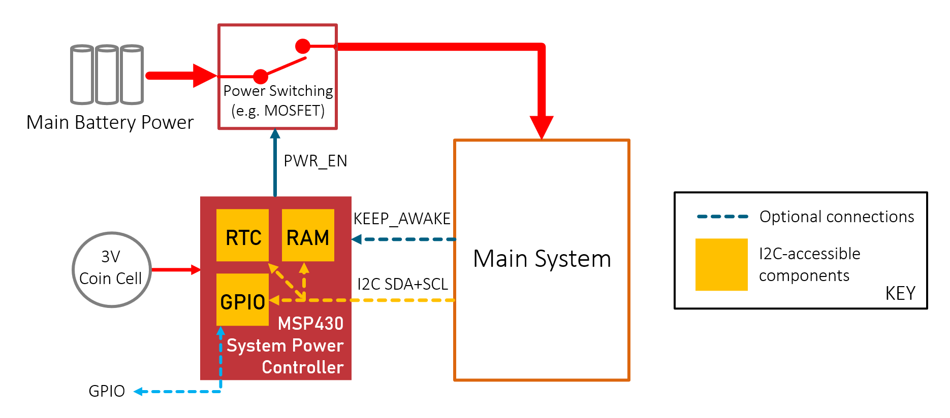
The circuit diagram below shows how the circuit is used. As mentioned, it operates from a coin cell, but you can also connect it to an external power rail too (for instance, if the main circuit has a 3.3V supply, that can be used). The core component is the MSP430 microcontroller.

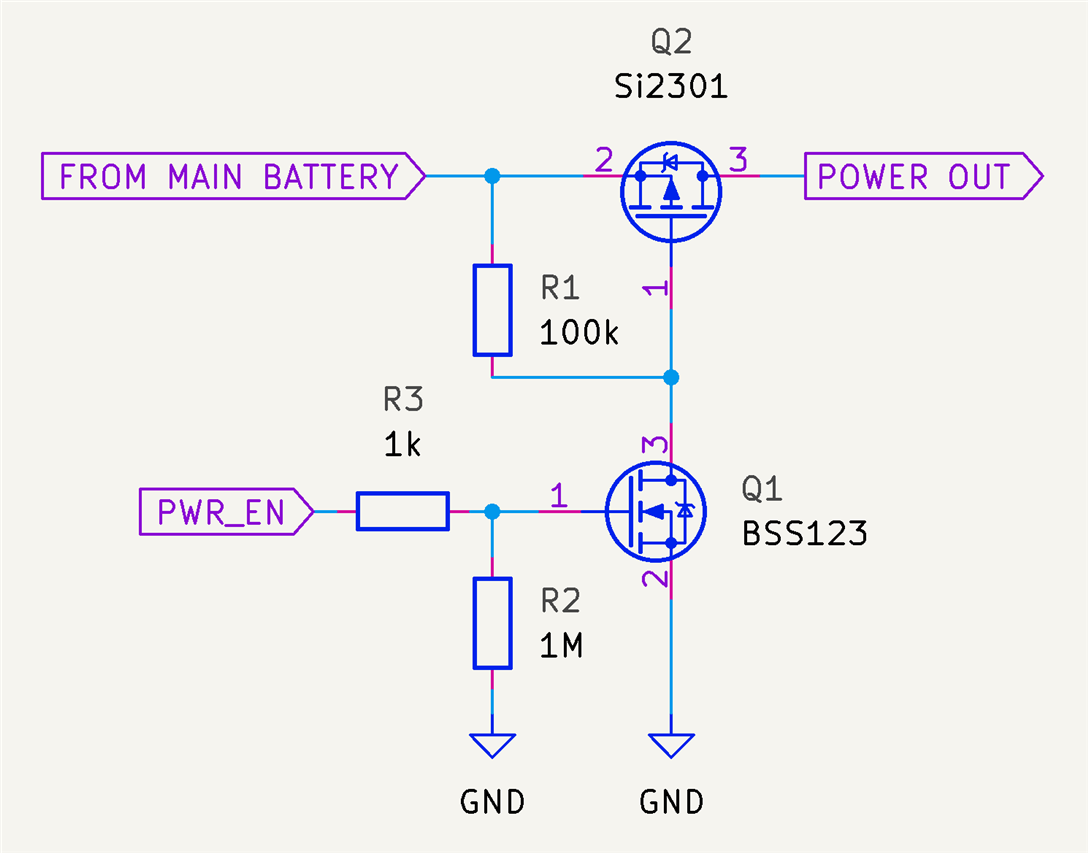
The PWR_EN pin is an output that switches on the power to the rest of the system. MOSFETs could be used to switch the power, as shown in the example below. This is just one option, it will depend on what is being powered.
The KEEP_AWAKE pin is an input to the MSP430 that can be used to keep the system awake for as long as desired. The MSP430 will read the KEEP_AWAKE pin value when power is enabled, and if the pin is high, then the power will continue to be kept enabled until the pin is set low. After it goes low, the KEEP_AWAKE pin won’t be read again until power is next enabled.
The IN0, IN1, OUT0, and OUT1 pins are general-purpose inputs/outputs that can be controlled via I2C. The IN0 pin also serves as an interrupt to power up the system, so it could be attached to a push button for instance, or it could be attached to some sort of trigger or sensor circuit if desired.
I2C Instruction Set
The I2C interface is optional. it’s not necessary to use the I2C interface if the default settings are satisfactory.
It is possible to issue I2C read or write instructions to address 0x40, to configure and operate the device. The I2C address is currently hard-coded to 0x40, but the code could be re-compiled with any value.
The general I2C procedure to send information to the device is to perform an I2C write transaction:
<start><address><instruction><data_1><data_2><data_n><stop>
The general I2C procedure to retrieve information from the device is to use two I2C transactions (the first being an I2C write, and the second being an I2C read):
<start><address><instruction><stop><start><address><read_data_1><read_data_2><read_data_n><stop>
Ten different functions, (a) to (j), are currently supported, as listed below. As an example, if it was desired to use function (a) to set the MSP430 to wake up the system every 45 seconds, the following pseudocode could be used:
address=0x40;buf[0]=0x66;buf[1]=45;i2c_write(address, buf, 2); // write 2 bytes to I2C address 0x40
If you wanted to use function (f) to read from RAM locations 10 to 15, the following pseudocode would be used:
address=0x40;buf[0]=10;i2c_write(address, buf, 1); // write 1 byte to select the RAM locationi2c_read(address, buf, 6); // read 6 bytes of RAM contentprint “RAM was read into buf[0] to buf[5]”;
The following section (a) to (j) documents all the I2C accessible features.
(a) Wake every n seconds (n is between 5 and 255)
Write Instruction: 0x66, data_1: n
(b) Wake every n minutes (n is between 1 and 255)
Write Instruction: 0x67, data_1: n
(c) Read Inputs
Write Instruction: 0x69
Read: n = read_data_1
Bits 0 and 1 of the byte n represent the two inputs. All other bits are to be ignored.
(d) Write Outputs
Write Instruction 0x70, data_1: n
Bits 0 and 1 of the byte n represent the two outputs. All other bits are ignored.
(e) Write to RAM
`Write Instruction i, data_1=n1, data_2=n2, …
The value i is an index between 0-63, to represent the memory locations 0-63. The values n1, n2, etc are any number of bytes to be written from that index location onward
(f) Read from RAM
Write instruction i
Read: n1=read_data_1, n2=read_data_2, …
The value i is an index between 0-63 to represent memory locations 0-63. The values read are retrieved from the index location onward
(g) Set RTC Time
Write Instruction 0x64, data_1=BCD_hour, data_2=BCD_min, data_3=BCD_sec, data_4=am_pm_indication
The values are in BCD format, for instance the 12th hour is represented by 0x12 hexadecimal. The am_pm_indication is 0 for AM, and 1 for PM.
(h) Set RTC Date
Write Instruction 0x65, data_1=year, data_2=month, data_3=date
The year is a value between 0 and 99, representing years since 2000, i.e. 2000 to 2099. The month is a value in the range 1-12. The date is in the range 1-31.
(i) Read RTC Time
Write Instruction 0x64
Read: BCD_hour=read_data_1, BCD_min=read_data_2, BCD_sec=read_data_3, am_pm_indication=read_data_4
See (g) to interpret the read values
(j) Read RTC Date
Write Instruction 0x65
Read: year=read_data_1, month=read_data_2, date=read_data_3
The year value read will be BCD encoded for the two least significant digits. For example if the year is 2022 then the year read will be 0x22. The month is BCD encoded too, but starting at zero. So, November would be read as 0x10. The date (0-31) is BCD encoded, for instance the 27th of the month will be read as 0x27.
Building It
This project really just consists of the microcontroller, and a few components, as shown in the earlier circuit diagram. To program the microcontroller, the simplest and most cost-effective way is to buy a MSP-EXP430G2ET Launchpad board. It contains a 20-pin DIP socket for programming. It is also possible to program the chip in-circuit. To do that, the following four connections are made:
| MSP430 Pin # | Programmer Pin Name | Notes |
| 1 (VCC) | VTARGET | Used by the programmer to detect target voltage |
| 20 (VSS) | GND | |
| 16 (RST/TDIO) | TDIO | |
| 17 (TCK) | TCK (via 330 ohm) | Connect a 330 ohm resistor in series |
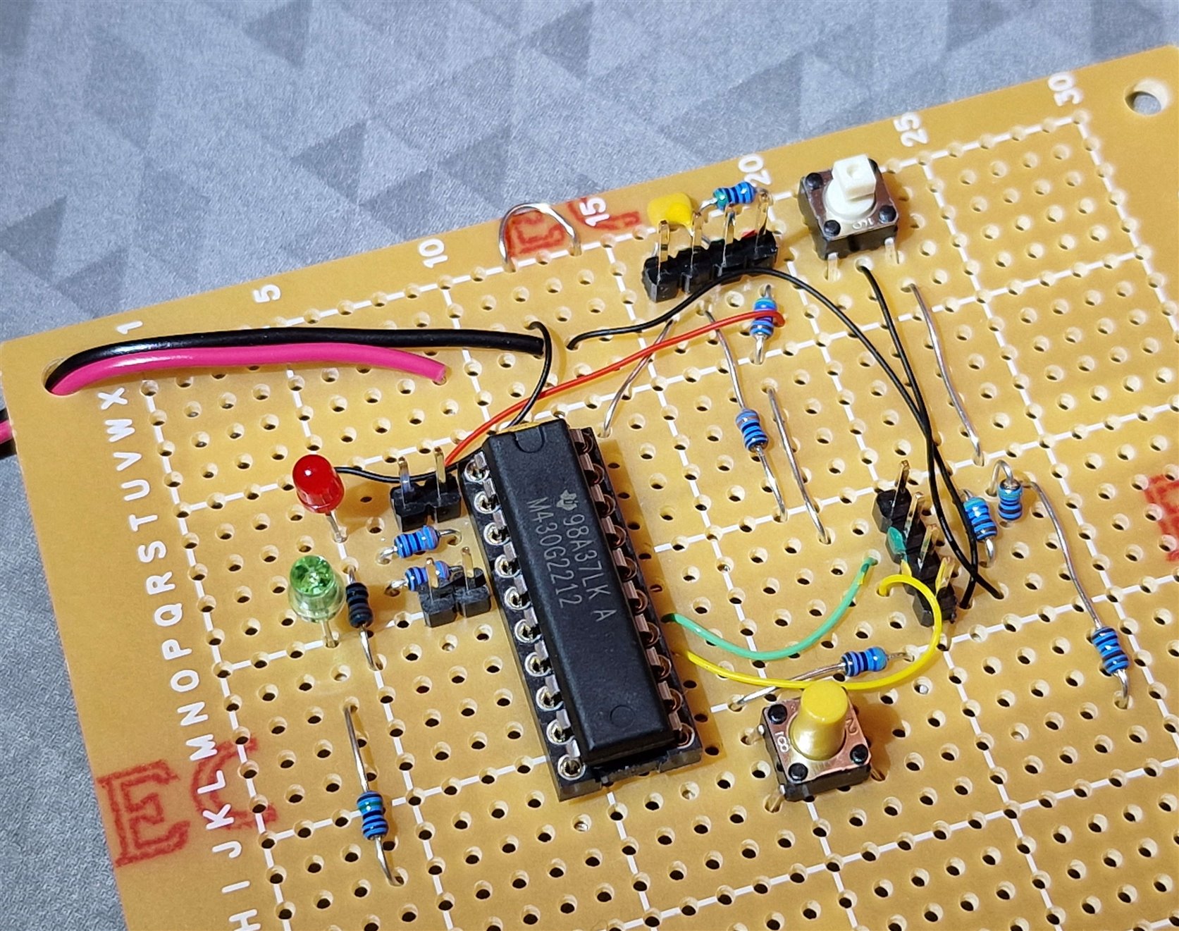
I tested the circuit on a piece of perfboard for now:
The source code is on GitHub, and it can be compiled using Code Composer Studio.
The main logic is in a single file called maincode.c, it can be edited if different functionality or default configuration tweaks are desired.
Note that nearly the entire Flash memory on the MSP430G2212 microcontroller is in use, so it will be difficult to add more features without removing some features. If you plan to add more features, then the MSP430G2452 can be used as a drop-in replacement, with four times the Flash capacity. However, it costs more.
Testing It
I decided to test the I2C interface using a Raspberry Pi 4, running I2C test code.
The code is on GitHub, at the same link as before, but in a folder called controller_test. (Note: the code will only run on a Pi 4; to use on older Pi models, it will need a code change which I have not got around to implementing).
To build the code, type make and then run the test by typing ./i2ctest
If the project is working correctly, the test will exercise some of the functionality, and the following output should be displayed.
pi@raspberrypi:~/development/controller_test$ make
g++ -Wall -I/usr/local/include -g -c -o i2cfunc.o i2cfunc.c
g++ -o i2ctest i2cfunc.o i2ctest.cpp -Wall -I/usr/local/include -g -lwiringPi
pi@raspberrypi:~/development/controller_test$ ./i2ctest
writing output
Reading inputs
input is 0x00
selecting address 0x00 and writing 10 bytes to RAM..
clearing local buffer..
reading 10 bytes from address 0 onward:
read 10 bytes: 0x01, 02, 03, 04, 05, 06, 07, 08, 09, 0a,
setting date to 27th June 2022
setting time to 1:19:01 AM
delaying 4 sec..
time is 01:19:05 0
changing wake rate to 10 sec
pi@raspberrypi:~/development/controller_test$
Summary
A simple, but reasonably flexible system power controller was built using an MSP430 microcontroller. It may come in handy for projects that are intended to run from batteries for long periods of time.
Thanks for reading!


