element14 Community
element14 Community
    Register Log In
  • Site
  • Search
  • Log In Register
  • About Us
  • Community Hub
    Community Hub
    • What's New on element14
    • Feedback and Support
    • Benefits of Membership
    • Personal Blogs
    • Members Area
    • Achievement Levels
  • Learn
    Learn
    • Ask an Expert
    • eBooks
    • element14 presents
    • Learning Center
    • Tech Spotlight
    • STEM Academy
    • Webinars, Training and Events
    • Learning Groups
  • Technologies
    Technologies
    • 3D Printing
    • FPGA
    • Industrial Automation
    • Internet of Things
    • Power & Energy
    • Sensors
    • Technology Groups
  • Challenges & Projects
    Challenges & Projects
    • Design Challenges
    • element14 presents Projects
    • Project14
    • Arduino Projects
    • Raspberry Pi Projects
    • Project Groups
  • Products
    Products
    • Arduino
    • Avnet Boards Community
    • Dev Tools
    • Manufacturers
    • Multicomp Pro
    • Product Groups
    • Raspberry Pi
    • RoadTests & Reviews
  • Store
    Store
    • Visit Your Store
    • Choose another store...
      • Europe
      •  Austria (German)
      •  Belgium (Dutch, French)
      •  Bulgaria (Bulgarian)
      •  Czech Republic (Czech)
      •  Denmark (Danish)
      •  Estonia (Estonian)
      •  Finland (Finnish)
      •  France (French)
      •  Germany (German)
      •  Hungary (Hungarian)
      •  Ireland
      •  Israel
      •  Italy (Italian)
      •  Latvia (Latvian)
      •  
      •  Lithuania (Lithuanian)
      •  Netherlands (Dutch)
      •  Norway (Norwegian)
      •  Poland (Polish)
      •  Portugal (Portuguese)
      •  Romania (Romanian)
      •  Russia (Russian)
      •  Slovakia (Slovak)
      •  Slovenia (Slovenian)
      •  Spain (Spanish)
      •  Sweden (Swedish)
      •  Switzerland(German, French)
      •  Turkey (Turkish)
      •  United Kingdom
      • Asia Pacific
      •  Australia
      •  China
      •  Hong Kong
      •  India
      •  Korea (Korean)
      •  Malaysia
      •  New Zealand
      •  Philippines
      •  Singapore
      •  Taiwan
      •  Thailand (Thai)
      • Americas
      •  Brazil (Portuguese)
      •  Canada
      •  Mexico (Spanish)
      •  United States
      Can't find the country/region you're looking for? Visit our export site or find a local distributor.
  • Translate
  • Profile
  • Settings
Experts, Learning and Guidance
  • Technologies
  • More
Experts, Learning and Guidance
Ask an Expert Forum Flexible PCBs; Any interest, and any tips? (NOT a discussion about specific PCB manufacturers, that will get reported, so no spam please : )
  • Blog
  • Forum
  • Documents
  • Leaderboard
  • Files
  • Members
  • Mentions
  • Sub-Groups
  • Tags
  • More
  • Cancel
  • New
Join Experts, Learning and Guidance to participate - click to join for free!
Actions
  • Share
  • More
  • Cancel
Forum Thread Details
  • Replies 28 replies
  • Subscribers 282 subscribers
  • Views 3922 views
  • Users 0 members are here
  • pcb manufacture
  • flexible pcb
  • pcb design
Related
See a helpful answer?

Be sure to click 'more' and select 'suggest as answer'!

If you're the thread creator, be sure to click 'more' then 'Verify as Answer'!

Flexible PCBs; Any interest, and any tips? (NOT a discussion about specific PCB manufacturers, that will get reported, so no spam please : )

shabaz
shabaz over 1 year ago

The cost of prototype flex PCBs seems to have come down a _lot_ with some (not all) prototype PCB manufacturers.

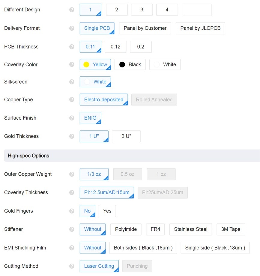
Here's an example quote from a popular (3-letter name) prototype PCB manufacturer, for a 2-layer 160x100mm board with a lot of holes (I randomly chose Gerber files for a normal FR4 project, to generate this quote for now), and ENIG finish by default. $33 for 5 boards, so $6.60 per board basically,. This might actually be cheaper than an FR4 ENIG board!

image

These are the options (default settings); the board thickness is 0.11mm:
image

Another popular PCB manufacturer (one that is famous for a lot of spam) is currently quoting $158 for five boards of similar size, so that's quite a difference!

I had a variety of general questions since I've never done a flex PCB design.

Could these be useful for perhaps creating membrane-style keyboards? I'm thinking that perhaps the solder mask might be thick enough to create separation between the flex PCB and (say) an FR4 base, to create a PCB maybe. Alternatively, a laser-cut sheet could be placed in between for added separation. Has anyone tried such a thing? I'm considering it for a keypad with many dozens of keys for a variant of this project:  Triggered Sound FX: On-the-Fly Sound Mixing with Pi Pico  

Are there any tips/tricks for flex PCBs? For instance, are there particular components or connectors that lend themselves to such use, and are some components best avoided? Any checklist you use for flex PCB designs?

Would you rarely apply components to a flex PCB (using it as an interconnect), or are you comfortable with components on them? Both sides or one side? : )

Has anyone tried soldering flex PCB directly to a FR4 PCB? I have done this with the flex on some LCD displays, and it is great; they have tiny holes for allowing the flux or excess solder to pop out of, and it works very well. I was wondering if the prototype flex PCB would behave the same as the flex on typical LCD screens.

Any problems with warpage, etc., i.e., if the flex PCB outline is intricate, will it curl up while it is being manufactured, potentially getting damaged?

Are any particular copper features or trace thicknesses best avoided for portions of flex that may be bent a lot (or even repeatedly)?

What applications do you have for flex PCBs? Are you considering them for any prototype or product, perhaps where you would typically not consider them, now that they are lower cost?

I apologize for all the questions, but I figure someone must ask the basic questions!

All comments are welcome! (apart from spam!).

  • Sign in to reply
  • Cancel

Top Replies

  • shabaz
    shabaz over 1 year ago +3
    Some research via Google images.. The style using metal springy domes is quite common, and the top surface can be plastic with raised bumps. I don't want a clicky tact-switch style keypad, but if that…
  • wolfgangfriedrich
    wolfgangfriedrich over 1 year ago +3
    Back in time, I did a collection of design and best practices articles. hackaday.io/.../164461-flex-pcb-design-information And probably the most impotant lesson I have learnt is, that a 2mil polyimide…
  • baldengineer
    baldengineer over 1 year ago in reply to shabaz +3
    Uneven heating is usually a different type of crack. It is possible that one side of the capacitor gets anchored, and then the other tries to move, creating a flex-like crack. Flex cracks start at the…
Parents
  • baldengineer
    baldengineer over 1 year ago

    One recommendation I would offer is to use MLCCs with "flexible terminations." Different vendors name it differently, but it is generally a layer of silver epoxy that allows the terminations (solder points) to flex slightly. On rigid PCBs, this pliable layer helps resist cracking when the board flexes. (The dreaded "board flex" failure.)

    Also, if you have a specific bend point in mind, I would recommend keeping MLCCs as far from it as possible. If you have to get close, keep the terminations in parallel with the radius so that both terminals (hopefully) see the same stresses.

    Or you can do what automotive customers do: put two caps in series but turn one of them 90 degrees.

    • Cancel
    • Vote Up +1 Vote Down
    • Sign in to reply
    • Cancel
  • shabaz
    shabaz over 1 year ago in reply to baldengineer

    Good point. I've hit this issue with normal FR4 and hot air tools too : ( To me 0402 decoupling capacitors (100nF or higher) seemed especially delicate compared to say 0603, and I've hit situations where the hot air didn't heat the component evenly when reflowing, and presumably micro-flexed the component, and ended up with shorted 0402 capacitors : ( After that I've also tried to avoid capacitors on regions of a board that may flex slightly.

    Neat idea with the orientated dual capacitors for some protection!!

    • Cancel
    • Vote Up 0 Vote Down
    • Sign in to reply
    • Cancel
  • anniel747
    anniel747 over 1 year ago in reply to shabaz
    This reply was deleted.
    • Cancel
    • Cancel
  • shabaz
    shabaz over 1 year ago in reply to anniel747

    You're right. I rarely do that (that board happened to be an RF project with a QFN that was being reflowed (the nearby 0402 capacitors were the casualties). I also probably didn't heat very evenly with the tool at the time. 

    • Cancel
    • Vote Up +1 Vote Down
    • Sign in to reply
    • Cancel
  • baldengineer
    baldengineer over 1 year ago in reply to shabaz

    Uneven heating is usually a different type of crack. It is possible that one side of the capacitor gets anchored, and then the other tries to move, creating a flex-like crack.

    Flex cracks start at the "bottom" of the termination and run at nearly a 45-degree angle towards the outside edge. (Imagine it breaking away, and you can probably imagine the fault line.)

    A thermal imbalance will cause a thermal crack—these cracks form along the electrode plate. If you cross-sectioned the capacitor, you would see the damage run along the length of the capacitor.

    Either crack can go undetected. Flex cracks are usually visible. Thermal cracks are not. And it may not be until moisture makes its way in that you realize a problem. (Unless you, for some reason, designed the board such that you can test every capacitor individually!)

    Ironically, I usually recommend hot air for MLCCs. Traditional soldering irons will very often introduce a thermal crack if the tip touches the electrode during soldering. The damage is less likely if the part/PCB is pre-heated. 

    If you think you're thermally cracking MLCCs with hot air, you might consider a pre-heat phase before ramping your air up to reflow temps.

    Edit. That said, I remembered a case where reflow ovens caused cracks. On larger parts, like 0805 or especially 1206+, if one side of the cap is connected to a huge ground plane, it's possible the PCB itself stress cracks the part from thermal expanasion. It is far rarer than traditional flex cracks, but under the right set of circumstances, it can happen.

    • Cancel
    • Vote Up +3 Vote Down
    • Sign in to reply
    • Cancel
Reply
  • baldengineer
    baldengineer over 1 year ago in reply to shabaz

    Uneven heating is usually a different type of crack. It is possible that one side of the capacitor gets anchored, and then the other tries to move, creating a flex-like crack.

    Flex cracks start at the "bottom" of the termination and run at nearly a 45-degree angle towards the outside edge. (Imagine it breaking away, and you can probably imagine the fault line.)

    A thermal imbalance will cause a thermal crack—these cracks form along the electrode plate. If you cross-sectioned the capacitor, you would see the damage run along the length of the capacitor.

    Either crack can go undetected. Flex cracks are usually visible. Thermal cracks are not. And it may not be until moisture makes its way in that you realize a problem. (Unless you, for some reason, designed the board such that you can test every capacitor individually!)

    Ironically, I usually recommend hot air for MLCCs. Traditional soldering irons will very often introduce a thermal crack if the tip touches the electrode during soldering. The damage is less likely if the part/PCB is pre-heated. 

    If you think you're thermally cracking MLCCs with hot air, you might consider a pre-heat phase before ramping your air up to reflow temps.

    Edit. That said, I remembered a case where reflow ovens caused cracks. On larger parts, like 0805 or especially 1206+, if one side of the cap is connected to a huge ground plane, it's possible the PCB itself stress cracks the part from thermal expanasion. It is far rarer than traditional flex cracks, but under the right set of circumstances, it can happen.

    • Cancel
    • Vote Up +3 Vote Down
    • Sign in to reply
    • Cancel
Children
  • shabaz
    shabaz over 1 year ago in reply to baldengineer

    Interesting info, I didn't realize the iron tip could damage from the body of the MLCC! I will take a lot more care in that respect from now on too.

    I had a pretty rotten hot-air tool at the time, now I have a much better one. Now the pre-heater + hot air tool are more usable. 

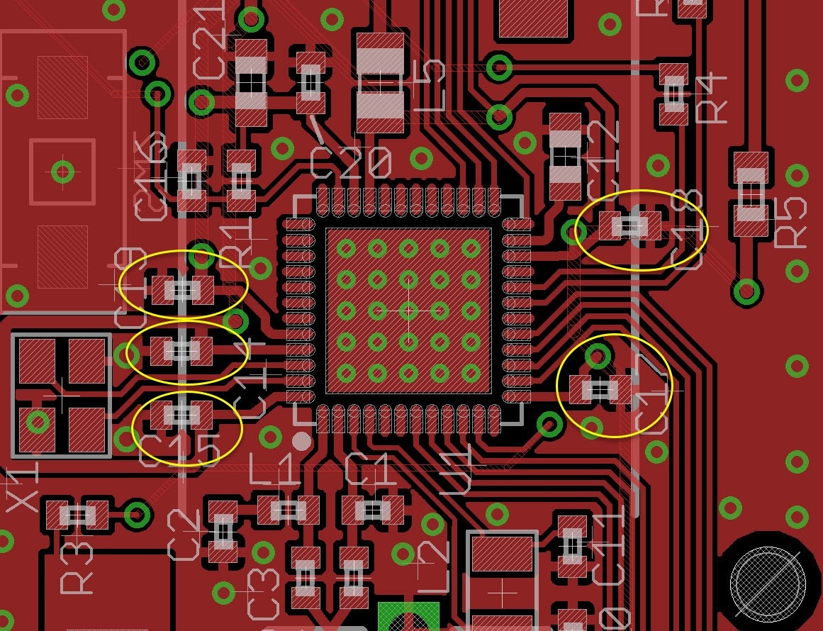
    I buy only decent brand MLCCs and only from distributors, they happened to be these ones. Still, they are merely 0.5 mm thick, and pack a decent capacitance. Since it was a decent brand, I'm convinced it was just bad personal technique and bad tools, so that was one driver to eventually replace the hot air tool for a better one. It was a combined radio + uC chip, with quite a few 100nF decoupling capacitors surrounding it (some of those are circled).

     image

    • Cancel
    • Vote Up 0 Vote Down
    • Sign in to reply
    • Cancel
  • shabaz
    shabaz over 1 year ago in reply to baldengineer

    At one workplace the simple rule was to not use 0402 if possible, they favoured 0603 or higher. I'm not sure of the mechanism, but wide pads were frowned upon for 0402 (i.e. the pad was barely wider than the component contact), because with wide pads, as well as causing the component to not solder straight, it could cause cracking somehow - perhaps a twisting motion as it cools? Also, fancy pad shapes were preferred for 0402 (with a taper inward) - apparently that created better success from the PCB factory that they used. 

    EDIT: also noticed in the PCB layout above, the 0402 footprints in the default EAGLE capacitor library 'RCL', has a width of 0.9mm! That is definitely way too wide. The KiCad default capacitor library has a more sensible 0.62mm width (although the actual component datasheet should be checked anyway).

    • Cancel
    • Vote Up +2 Vote Down
    • Sign in to reply
    • Cancel
element14 Community

element14 is the first online community specifically for engineers. Connect with your peers and get expert answers to your questions.

  • Members
  • Learn
  • Technologies
  • Challenges & Projects
  • Products
  • Store
  • About Us
  • Feedback & Support
  • FAQs
  • Terms of Use
  • Privacy Policy
  • Legal and Copyright Notices
  • Sitemap
  • Cookies

An Avnet Company © 2025 Premier Farnell Limited. All Rights Reserved.

Premier Farnell Ltd, registered in England and Wales (no 00876412), registered office: Farnell House, Forge Lane, Leeds LS12 2NE.

ICP 备案号 10220084.

Follow element14

  • X
  • Facebook
  • linkedin
  • YouTube