element14 Community
element14 Community
    Register Log In
  • Site
  • Search
  • Log In Register
  • About Us
  • Community Hub
    Community Hub
    • What's New on element14
    • Feedback and Support
    • Benefits of Membership
    • Personal Blogs
    • Members Area
    • Achievement Levels
  • Learn
    Learn
    • Ask an Expert
    • eBooks
    • element14 presents
    • Learning Center
    • Tech Spotlight
    • STEM Academy
    • Webinars, Training and Events
    • Learning Groups
  • Technologies
    Technologies
    • 3D Printing
    • FPGA
    • Industrial Automation
    • Internet of Things
    • Power & Energy
    • Sensors
    • Technology Groups
  • Challenges & Projects
    Challenges & Projects
    • Design Challenges
    • element14 presents Projects
    • Project14
    • Arduino Projects
    • Raspberry Pi Projects
    • Project Groups
  • Products
    Products
    • Arduino
    • Avnet Boards Community
    • Dev Tools
    • Manufacturers
    • Multicomp Pro
    • Product Groups
    • Raspberry Pi
    • RoadTests & Reviews
  • Store
    Store
    • Visit Your Store
    • Choose another store...
      • Europe
      •  Austria (German)
      •  Belgium (Dutch, French)
      •  Bulgaria (Bulgarian)
      •  Czech Republic (Czech)
      •  Denmark (Danish)
      •  Estonia (Estonian)
      •  Finland (Finnish)
      •  France (French)
      •  Germany (German)
      •  Hungary (Hungarian)
      •  Ireland
      •  Israel
      •  Italy (Italian)
      •  Latvia (Latvian)
      •  
      •  Lithuania (Lithuanian)
      •  Netherlands (Dutch)
      •  Norway (Norwegian)
      •  Poland (Polish)
      •  Portugal (Portuguese)
      •  Romania (Romanian)
      •  Russia (Russian)
      •  Slovakia (Slovak)
      •  Slovenia (Slovenian)
      •  Spain (Spanish)
      •  Sweden (Swedish)
      •  Switzerland(German, French)
      •  Turkey (Turkish)
      •  United Kingdom
      • Asia Pacific
      •  Australia
      •  China
      •  Hong Kong
      •  India
      •  Korea (Korean)
      •  Malaysia
      •  New Zealand
      •  Philippines
      •  Singapore
      •  Taiwan
      •  Thailand (Thai)
      • Americas
      •  Brazil (Portuguese)
      •  Canada
      •  Mexico (Spanish)
      •  United States
      Can't find the country/region you're looking for? Visit our export site or find a local distributor.
  • Translate
  • Profile
  • Settings
Experts, Learning and Guidance
  • Technologies
  • More
Experts, Learning and Guidance
Ask an Expert Forum Flexible PCBs; Any interest, and any tips? (NOT a discussion about specific PCB manufacturers, that will get reported, so no spam please : )
  • Blog
  • Forum
  • Documents
  • Leaderboard
  • Files
  • Members
  • Mentions
  • Sub-Groups
  • Tags
  • More
  • Cancel
  • New
Join Experts, Learning and Guidance to participate - click to join for free!
Actions
  • Share
  • More
  • Cancel
Forum Thread Details
  • Replies 28 replies
  • Subscribers 282 subscribers
  • Views 3918 views
  • Users 0 members are here
  • pcb manufacture
  • flexible pcb
  • pcb design
Related
See a helpful answer?

Be sure to click 'more' and select 'suggest as answer'!

If you're the thread creator, be sure to click 'more' then 'Verify as Answer'!

Flexible PCBs; Any interest, and any tips? (NOT a discussion about specific PCB manufacturers, that will get reported, so no spam please : )

shabaz
shabaz over 1 year ago

The cost of prototype flex PCBs seems to have come down a _lot_ with some (not all) prototype PCB manufacturers.

Here's an example quote from a popular (3-letter name) prototype PCB manufacturer, for a 2-layer 160x100mm board with a lot of holes (I randomly chose Gerber files for a normal FR4 project, to generate this quote for now), and ENIG finish by default. $33 for 5 boards, so $6.60 per board basically,. This might actually be cheaper than an FR4 ENIG board!

image

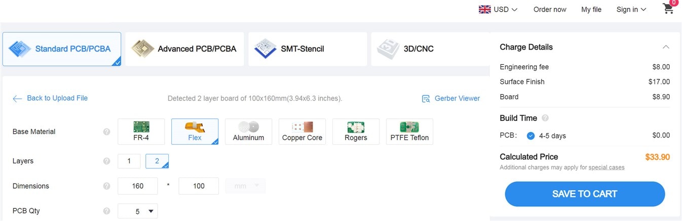
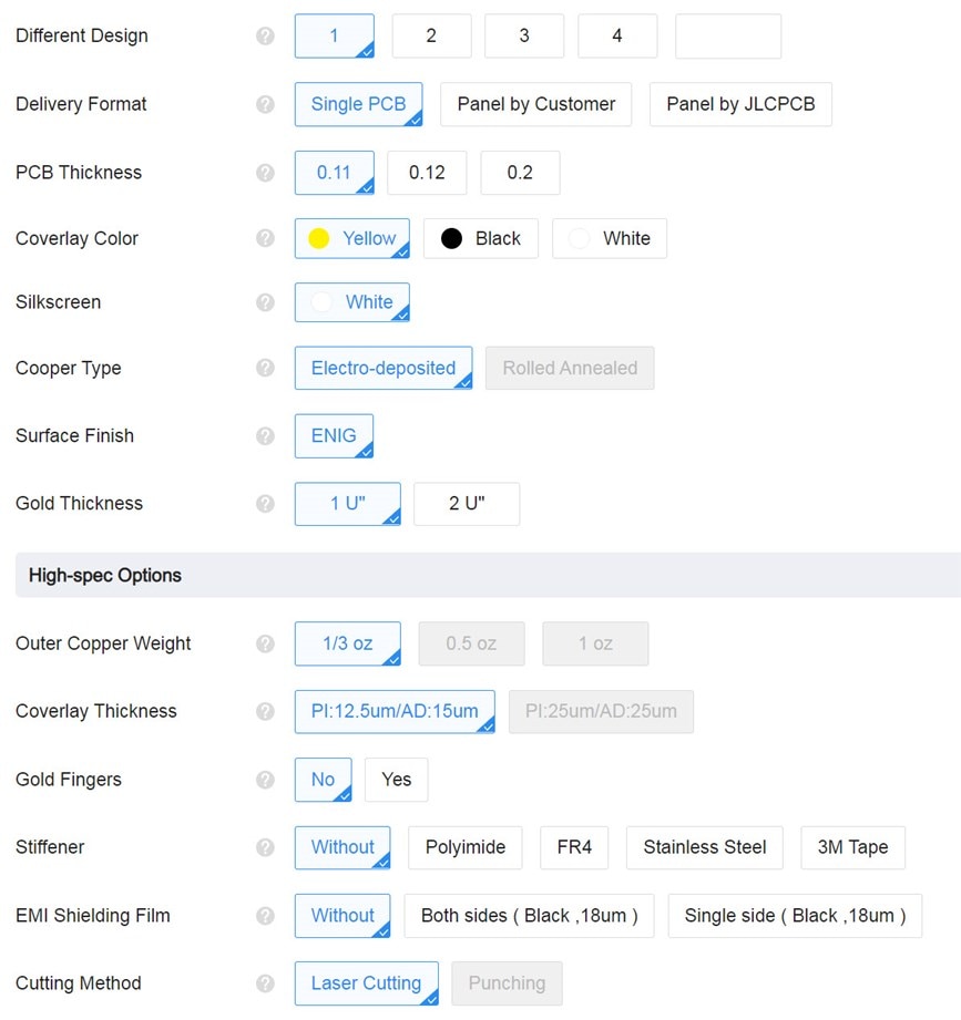
These are the options (default settings); the board thickness is 0.11mm:

image

Another popular PCB manufacturer (one that is famous for a lot of spam) is currently quoting $158 for five boards of similar size, so that's quite a difference!

I had a variety of general questions since I've never done a flex PCB design.

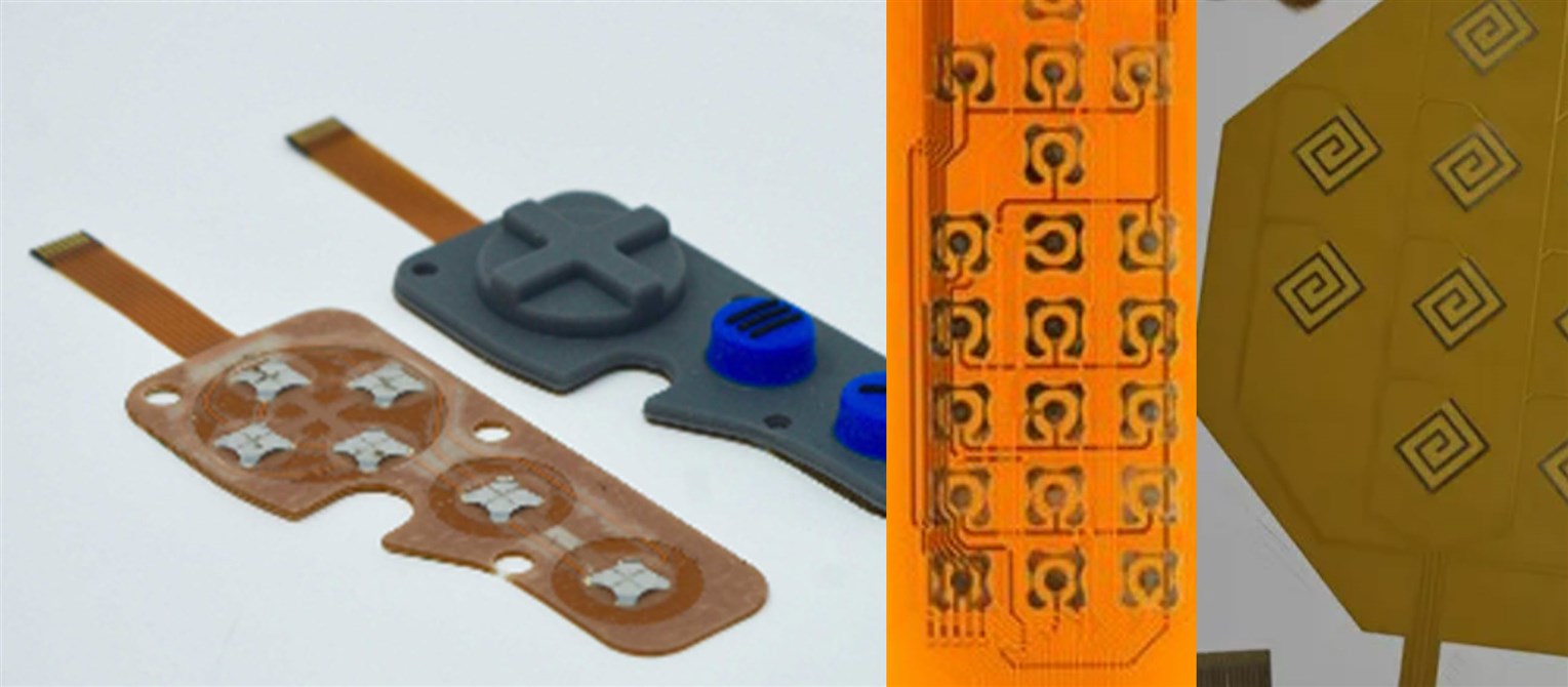
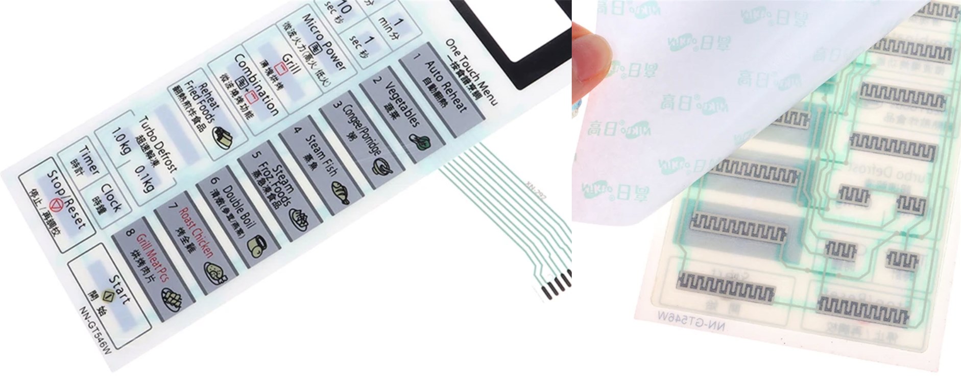
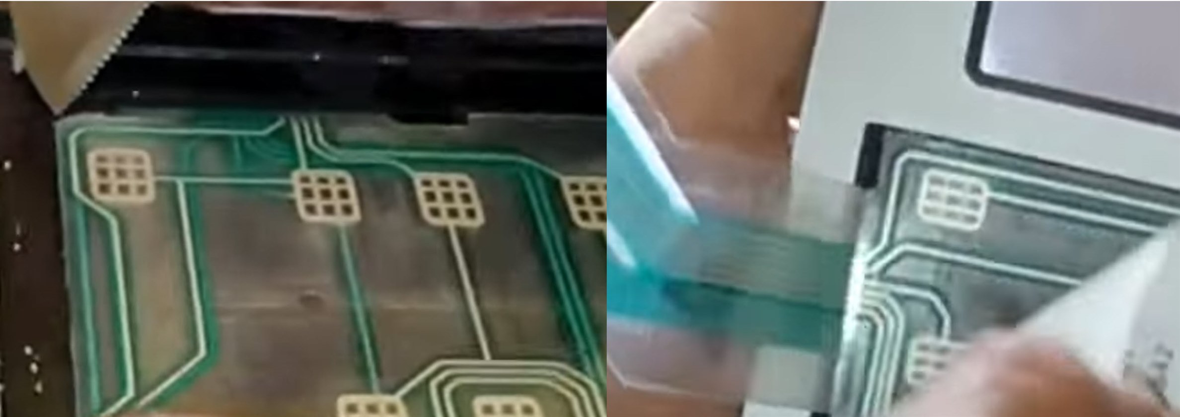
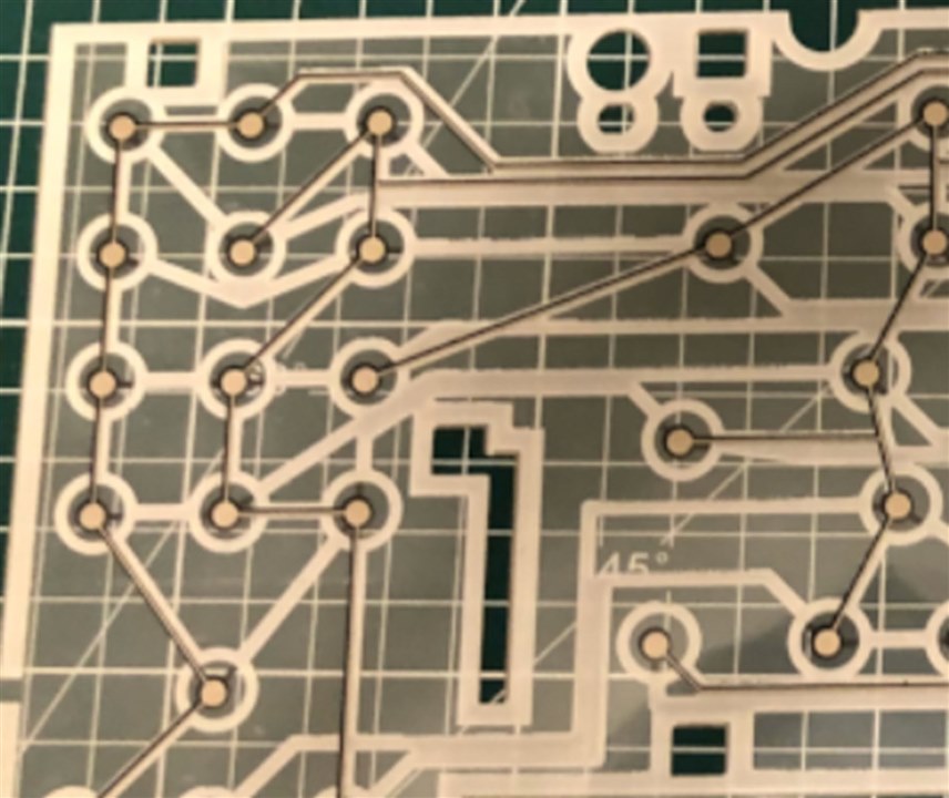
Could these be useful for perhaps creating membrane-style keyboards? I'm thinking that perhaps the solder mask might be thick enough to create separation between the flex PCB and (say) an FR4 base, to create a PCB maybe. Alternatively, a laser-cut sheet could be placed in between for added separation. Has anyone tried such a thing? I'm considering it for a keypad with many dozens of keys for a variant of this project:  Triggered Sound FX: On-the-Fly Sound Mixing with Pi Pico  

Are there any tips/tricks for flex PCBs? For instance, are there particular components or connectors that lend themselves to such use, and are some components best avoided? Any checklist you use for flex PCB designs?

Would you rarely apply components to a flex PCB (using it as an interconnect), or are you comfortable with components on them? Both sides or one side? : )

Has anyone tried soldering flex PCB directly to a FR4 PCB? I have done this with the flex on some LCD displays, and it is great; they have tiny holes for allowing the flux or excess solder to pop out of, and it works very well. I was wondering if the prototype flex PCB would behave the same as the flex on typical LCD screens.

Any problems with warpage, etc., i.e., if the flex PCB outline is intricate, will it curl up while it is being manufactured, potentially getting damaged?

Are any particular copper features or trace thicknesses best avoided for portions of flex that may be bent a lot (or even repeatedly)?

What applications do you have for flex PCBs? Are you considering them for any prototype or product, perhaps where you would typically not consider them, now that they are lower cost?

I apologize for all the questions, but I figure someone must ask the basic questions!

All comments are welcome! (apart from spam!).

  • Sign in to reply
  • Cancel

Top Replies

  • shabaz
    shabaz over 1 year ago +3
    Some research via Google images.. The style using metal springy domes is quite common, and the top surface can be plastic with raised bumps. I don't want a clicky tact-switch style keypad, but if that…
  • wolfgangfriedrich
    wolfgangfriedrich over 1 year ago +3
    Back in time, I did a collection of design and best practices articles. hackaday.io/.../164461-flex-pcb-design-information And probably the most impotant lesson I have learnt is, that a 2mil polyimide…
  • baldengineer
    baldengineer over 1 year ago in reply to shabaz +3
    Uneven heating is usually a different type of crack. It is possible that one side of the capacitor gets anchored, and then the other tries to move, creating a flex-like crack. Flex cracks start at the…
  • genebren
    genebren over 1 year ago

    This is an interesting topic and some great questions.  Unfortunately, I don't have any answers given a lack of experience in this area, but I do look forward to hearing as I have found myself wondering about if flex boards might be needed somewhere in my future.

    • Cancel
    • Vote Up +1 Vote Down
    • Sign in to reply
    • Cancel
  • Gough Lui
    Gough Lui over 1 year ago
    shabaz said:
    Could these be useful for perhaps creating membrane-style keyboards?

    Perhaps, but I'd be a bit nervous given the flat structure. Most membranes have a thick mylar sheet with holes or formed "indents" to increase separation. I'm not sure the mask will be enough in the long run, as the copper can elongate under lots of bending.

    shabaz said:
    For instance, are there particular components or connectors that lend themselves to such use, and are some components best avoided?

    Master the use of stiffeners under flexible PCBs - they're basically like glued on bits of substrate that can keep sections of the flex flat and relatively rigid. This is where I would mount my components to - any component mounted above flex that has no stiffener will likely peel off given enough bending, so usually you'd use the flexy-part as an interconnect ribbon (similar to how an inkjet printer uses them to connect the print head to the mainboard). If you design the end right, you could even get it to fit into a flexible flat connector socket for an ordinary rigid PCB, simplifying connectivity, as soldering while possible is often finnicky and risky as overheating is much more damaging to flex.

    shabaz said:
    Has anyone tried soldering flex PCB directly to a FR4 PCB?

    I have, it works as long as you're moderately skilled at soldering ... my students, however, make a mess of this.

    shabaz said:
    bent a lot (or even repeatedly)?

    I can't be considered an expert, but one has to be really careful of the bending radius if they want to repeatedly bend. Folding is generally only good for a few times at the most or the copper will develop fatigue cracks. I tend to make the copper traces as thick as possible to reduce failure risk especially in fatigue, but I've seen very fine traces work okay.

    Just think about the fact that hard disk head stacks are connected to the mainboard using a flexible printed circuit board and they have to last the lifetime of the disk in terms of seek operations (could be billions). I've never seen it fail - in part because there's enough slack. But those differential pairs going to the head are quite thin ...

    - Gough

    • Cancel
    • Vote Up +2 Vote Down
    • Sign in to reply
    • Cancel
  • dougw
    dougw over 1 year ago

    We do a lot of rigid/flex where the component areas are FR4 and the flex allows the rigid sections to be at different angles.

    We have noticed a couple of manufacturers have dramatically reduced prices.

    Large components on flex, especially BGAs probably should have stiffeners glued under the components on the other side of the flex.

    Our flex PCBs usually have rigid frames to maintain dimensional accuracy during CCA component stuffing. (The frame adds to the cost)

    I think it is recommended to have copper on only one side of flex where it is repeatedly flexed.

    • Cancel
    • Vote Up +1 Vote Down
    • Sign in to reply
    • Cancel
  • baldengineer
    baldengineer over 1 year ago

    One recommendation I would offer is to use MLCCs with "flexible terminations." Different vendors name it differently, but it is generally a layer of silver epoxy that allows the terminations (solder points) to flex slightly. On rigid PCBs, this pliable layer helps resist cracking when the board flexes. (The dreaded "board flex" failure.)

    Also, if you have a specific bend point in mind, I would recommend keeping MLCCs as far from it as possible. If you have to get close, keep the terminations in parallel with the radius so that both terminals (hopefully) see the same stresses.

    Or you can do what automotive customers do: put two caps in series but turn one of them 90 degrees.

    • Cancel
    • Vote Up +1 Vote Down
    • Sign in to reply
    • Cancel
  • shabaz
    shabaz over 1 year ago in reply to Gough Lui

    I think you're right, for a keyboard, the gap between the contacts would be way too thin with just solder resist. A layer of "something" more thicker in the sandwich is needed.

    Regarding copper elongation over time in such a keyboard, I was thinking an option might be to use the flex PCB just as a way of electrical contact delivery and not for if's springiness, for instance, by having a circular cut-out around each pad for about 340 degrees or so, and then sticking a firmer thin sheet of plastic on top with the legends, so that the top sheet is being used for its springiness, rather than the flexible PCB. But that could cause its own issues, for instance, tearing at the traces over time since they would flex, maybe buckle a tiny amount each time. Maybe it's only feasible for non-critical stuff with a built-in lifetime.

    • Cancel
    • Vote Up 0 Vote Down
    • Sign in to reply
    • Cancel
  • shabaz
    shabaz over 1 year ago in reply to dougw

    The manufacturer doesn't offer the rigid portion capability on that service, I suspect that would cost a lot more, but I guess there are DIY techniques that could be used, e.g. combine the flex PCB with a separate thin FR4 board for the portions where the large components need to go. I guess that's the best of both worlds, combine a flexible PCB design with normal FR4, using the flex for all the more interconnect areas and maybe smaller components if needed!

    • Cancel
    • Vote Up 0 Vote Down
    • Sign in to reply
    • Cancel
  • shabaz
    shabaz over 1 year ago in reply to baldengineer

    Good point. I've hit this issue with normal FR4 and hot air tools too : ( To me 0402 decoupling capacitors (100nF or higher) seemed especially delicate compared to say 0603, and I've hit situations where the hot air didn't heat the component evenly when reflowing, and presumably micro-flexed the component, and ended up with shorted 0402 capacitors : ( After that I've also tried to avoid capacitors on regions of a board that may flex slightly.

    Neat idea with the orientated dual capacitors for some protection!!

    • Cancel
    • Vote Up 0 Vote Down
    • Sign in to reply
    • Cancel
  • shabaz
    shabaz over 1 year ago

    Some research via Google images..

    The style using metal springy domes is quite common, and the top surface can be plastic with raised bumps. I don't want a clicky tact-switch style keypad, but if that was needed, then this looks like something that could be done with a rigid PCB too, although the benefit with the flexible PCB is that the connecting flex is integrated.

    The spiral thing on the right doesn't use a dome I think. No info on any of these, all I could find were low-res images.

    image

    Next I looked at microwave control panels. Interesting how one layer has solid rectangle pads, and the other has the meandering pattern. I think the contacts are covered in conducting carbon.

    Perhaps the meandering pattern allows for more pressure on the edges, to make a better electrical contact.

    image

    Here's another microwave panel, this time with a pattern on both sheets. I think the pattern is horizontal lines on one sheet, and vertical lines on the other, making it look like square hatches. Again this could be to increase the contact pressure at those interfacing points. The pads look like they may be silvered.

    image

    Old-fashioned home computer keyboard:

    image

    This membrane was covered with plastic keys on springs, and I think the larger circles are insulating deposits of rubbery ink (on one sheet, in the sandwich filling area), and the springs sat on top of that circular area. When the key was pressed, only the center portion was pressed. I could be wrong, I'm going by memory. The weird shaped cut-outs are where the base plastic had protrusions. I think they prevent the sheet from slipping or expanding too much across the whole length perhaps.

    • Cancel
    • Vote Up +3 Vote Down
    • Sign in to reply
    • Cancel
  • wolfgangfriedrich
    wolfgangfriedrich over 1 year ago

    Back in time,  I did a collection of design and best practices articles.

    hackaday.io/.../164461-flex-pcb-design-information

    And probably the most impotant lesson I have learnt is, that a 2mil polyimide with single sided copper traces flex stackup is flexible. A 5mil with two-sided 2oz copper planes not so much. 

    • Cancel
    • Vote Up +3 Vote Down
    • Sign in to reply
    • Cancel
  • shabaz
    shabaz over 1 year ago in reply to wolfgangfriedrich

    Hi Wolfgang,

    That's brilliant.. I've downloaded all the documents to read! After all that, I think I will have decent confidence to move forward. I will probably create a test board with different features on it, to get to know the material, it will have various membrane button attempts on it too. It will be nice to get some experience with the material.

    I have a sheet of double-sided copper-clad flexible PCB which I've occasionally been using small offcuts of without etching, and the one I have is not thick copper but does feel somewhat stiff due to the large copper areas, so I can only imagine that 2oz would have indeed been quite stiff.

    • Cancel
    • Vote Up 0 Vote Down
    • Sign in to reply
    • Cancel
>
element14 Community

element14 is the first online community specifically for engineers. Connect with your peers and get expert answers to your questions.

  • Members
  • Learn
  • Technologies
  • Challenges & Projects
  • Products
  • Store
  • About Us
  • Feedback & Support
  • FAQs
  • Terms of Use
  • Privacy Policy
  • Legal and Copyright Notices
  • Sitemap
  • Cookies

An Avnet Company © 2025 Premier Farnell Limited. All Rights Reserved.

Premier Farnell Ltd, registered in England and Wales (no 00876412), registered office: Farnell House, Forge Lane, Leeds LS12 2NE.

ICP 备案号 10220084.

Follow element14

  • X
  • Facebook
  • linkedin
  • YouTube