Hello,
As a follow-up to my previous question, I have written a little program for the PIC16F628A that I had been lying around for quite a while. It works well, but I have to make sure the "PowerLoss" signal is seen by both the PIC and the OrangePi.
As the PIC works at 5V and the Orange Pi at 3.3V without being 5V tolerant, I have to shift the levels between both sides. After looking around, I found the AN97055 application note from Philips that mentions a single NMOS level shifter and even recommends using a BSS88 that I also had around.
However, after having wired it in a way that I believe is right, I noticed that when PowerLoss "pulls down" the 5V side, the 3.3V side is not event close to zero volts, but rather around 1.3 volts. This is not liked by the H3 inside the OrangePi as it freezes itself after a while and I have to reboot it.
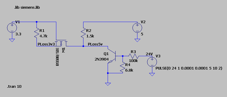
I tried to simulate the circuit with LTSpice and while it does not have the BSS88 by default, I found a library for it in the Blackboard project at github and so was able to create the following simulation:

Version 4
SHEET 1 1572 680
WIRE -128 0 -288 0
WIRE 0 0 -128 0
WIRE 528 0 176 0
WIRE -128 32 -128 0
WIRE 176 32 176 0
WIRE -288 112 -288 80
WIRE 0 112 0 0
WIRE 528 112 528 80
WIRE -128 160 -128 112
WIRE -64 160 -128 160
WIRE -16 160 -64 160
WIRE 176 160 176 112
WIRE 176 160 80 160
WIRE 256 160 176 160
WIRE 336 160 256 160
WIRE 336 176 336 160
WIRE 432 224 400 224
WIRE 464 224 432 224
WIRE 608 224 544 224
WIRE 624 224 608 224
WIRE 432 256 432 224
WIRE 336 336 336 272
WIRE 432 336 336 336
WIRE 624 336 624 304
WIRE 336 400 336 336
FLAG 336 400 0
FLAG -288 112 0
FLAG 528 112 0
FLAG 624 336 0
FLAG -64 160 PLoss3v3
FLAG 256 160 PLoss5v
FLAG 608 224 24V
SYMBOL voltage -288 -16 R0
WINDOW 123 0 0 Left 0
WINDOW 39 0 0 Left 0
SYMATTR InstName V1
SYMATTR Value 3.3
SYMBOL voltage 528 -16 R0
WINDOW 123 0 0 Left 0
WINDOW 39 0 0 Left 0
SYMATTR InstName V2
SYMATTR Value 5
SYMBOL voltage 624 208 R0
WINDOW 123 0 0 Left 0
WINDOW 39 0 0 Left 0
SYMATTR InstName V3
SYMATTR Value PULSE(0 24 1 0.0001 0.0001 5 10 2)
SYMBOL npn 400 176 M0
SYMATTR InstName Q1
SYMATTR Value 2N3904
SYMBOL res -144 16 R0
SYMATTR InstName R1
SYMATTR Value 4.7k
SYMBOL res 160 16 R0
SYMATTR InstName R2
SYMATTR Value 1.5k
SYMBOL res 560 208 R90
WINDOW 0 0 56 VBottom 2
WINDOW 3 32 56 VTop 2
SYMATTR InstName R3
SYMATTR Value 100k
SYMBOL res 416 240 R0
SYMATTR InstName R4
SYMATTR Value 6.8k
SYMBOL nmos 80 112 R90
SYMATTR InstName M1
SYMATTR Value BSS88/SIE
SYMATTR Prefix X
TEXT -320 424 Left 2 !.tran 10
TEXT -272 -96 Left 2 !.lib siemens.lib
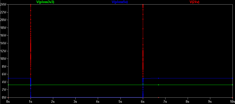
Tracing the voltages, it's not even giving the 1.3 volts that I measure on the "real thing" :

Now, maybe the library that I found is bogus, but maybe I also forgot something here.
One thing that I noticed is that the LTSpice symbol is not showing the "parasitic" diode on the N channel mosfet, while the application note clearly says that it's integral to the behavior of this arrangement.
Adding a single diode across the S and D makes the levels work properly, but then I figured that I could go with just a Schottky diode as I'm only ever interested in the 5V side pulling down the 3.3V side, not the other way around. A simple 1N5819 being enough, I'm all sorted, but I'm posting here in the hope of learning what I missed both in the simulation and the real life arrangement.
