element14 Community
element14 Community
    Register Log In
  • Site
  • Search
  • Log In Register
  • Community Hub
    Community Hub
    • What's New on element14
    • Feedback and Support
    • Benefits of Membership
    • Personal Blogs
    • Members Area
    • Achievement Levels
  • Learn
    Learn
    • Ask an Expert
    • eBooks
    • element14 presents
    • Learning Center
    • Tech Spotlight
    • STEM Academy
    • Webinars, Training and Events
    • Learning Groups
  • Technologies
    Technologies
    • 3D Printing
    • FPGA
    • Industrial Automation
    • Internet of Things
    • Power & Energy
    • Sensors
    • Technology Groups
  • Challenges & Projects
    Challenges & Projects
    • Design Challenges
    • element14 presents Projects
    • Project14
    • Arduino Projects
    • Raspberry Pi Projects
    • Project Groups
  • Products
    Products
    • Arduino
    • Avnet Boards Community
    • Dev Tools
    • Manufacturers
    • Multicomp Pro
    • Product Groups
    • Raspberry Pi
    • RoadTests & Reviews
  • Store
    Store
    • Visit Your Store
    • Choose another store...
      • Europe
      •  Austria (German)
      •  Belgium (Dutch, French)
      •  Bulgaria (Bulgarian)
      •  Czech Republic (Czech)
      •  Denmark (Danish)
      •  Estonia (Estonian)
      •  Finland (Finnish)
      •  France (French)
      •  Germany (German)
      •  Hungary (Hungarian)
      •  Ireland
      •  Israel
      •  Italy (Italian)
      •  Latvia (Latvian)
      •  
      •  Lithuania (Lithuanian)
      •  Netherlands (Dutch)
      •  Norway (Norwegian)
      •  Poland (Polish)
      •  Portugal (Portuguese)
      •  Romania (Romanian)
      •  Russia (Russian)
      •  Slovakia (Slovak)
      •  Slovenia (Slovenian)
      •  Spain (Spanish)
      •  Sweden (Swedish)
      •  Switzerland(German, French)
      •  Turkey (Turkish)
      •  United Kingdom
      • Asia Pacific
      •  Australia
      •  China
      •  Hong Kong
      •  India
      •  Korea (Korean)
      •  Malaysia
      •  New Zealand
      •  Philippines
      •  Singapore
      •  Taiwan
      •  Thailand (Thai)
      • Americas
      •  Brazil (Portuguese)
      •  Canada
      •  Mexico (Spanish)
      •  United States
      Can't find the country/region you're looking for? Visit our export site or find a local distributor.
  • Translate
  • Profile
  • Settings
Experts, Learning and Guidance
  • Technologies
  • More
Experts, Learning and Guidance
Ask an Expert Forum Single Mosfet level shifter does not appear to work
  • Blog
  • Forum
  • Documents
  • Leaderboard
  • Files
  • Members
  • Mentions
  • Sub-Groups
  • Tags
  • More
  • Cancel
  • New
Join Experts, Learning and Guidance to participate - click to join for free!
Actions
  • Share
  • More
  • Cancel
Forum Thread Details
  • State Not Answered
  • Replies 32 replies
  • Subscribers 267 subscribers
  • Views 1322 views
  • Users 0 members are here
Related
See a helpful answer?

Be sure to click 'more' and select 'suggest as answer'!

If you're the thread creator, be sure to click 'more' then 'Verify as Answer'!

Single Mosfet level shifter does not appear to work

obones
obones 1 month ago

Hello,

As a follow-up to my previous question, I have written a little program for the PIC16F628A that I had been lying around for quite a while. It works well, but I have to make sure the "PowerLoss" signal is seen by both the PIC and the OrangePi.
As the PIC works at 5V and the Orange Pi at 3.3V without being 5V tolerant, I have to shift the levels between both sides. After looking around, I found the AN97055 application note from Philips that mentions a single NMOS level shifter and even recommends using a BSS88 that I also had around.

However, after having wired it in a way that I believe is right, I noticed that when PowerLoss "pulls down" the 5V side, the 3.3V side is not event close to zero volts, but rather around 1.3 volts. This is not liked by the H3 inside the OrangePi as it freezes itself after a while and I have to reboot it.

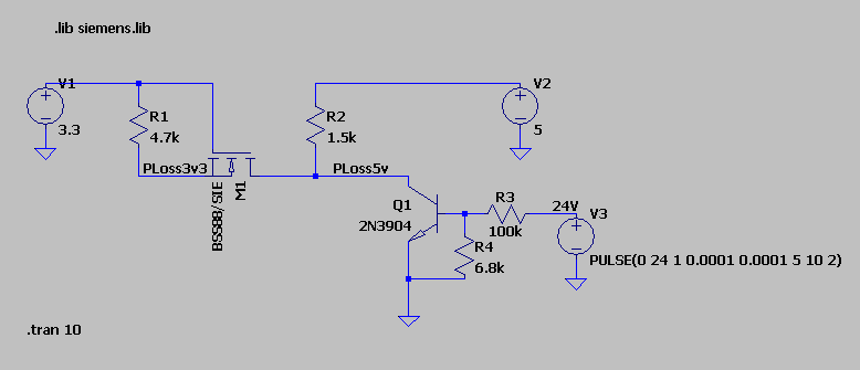
I tried to simulate the circuit with LTSpice and while it does not have the BSS88 by default, I found a library for it in the Blackboard project at github and so was able to create the following simulation:
image

Version 4
SHEET 1 1572 680
WIRE -128 0 -288 0
WIRE 0 0 -128 0
WIRE 528 0 176 0
WIRE -128 32 -128 0
WIRE 176 32 176 0
WIRE -288 112 -288 80
WIRE 0 112 0 0
WIRE 528 112 528 80
WIRE -128 160 -128 112
WIRE -64 160 -128 160
WIRE -16 160 -64 160
WIRE 176 160 176 112
WIRE 176 160 80 160
WIRE 256 160 176 160
WIRE 336 160 256 160
WIRE 336 176 336 160
WIRE 432 224 400 224
WIRE 464 224 432 224
WIRE 608 224 544 224
WIRE 624 224 608 224
WIRE 432 256 432 224
WIRE 336 336 336 272
WIRE 432 336 336 336
WIRE 624 336 624 304
WIRE 336 400 336 336
FLAG 336 400 0
FLAG -288 112 0
FLAG 528 112 0
FLAG 624 336 0
FLAG -64 160 PLoss3v3
FLAG 256 160 PLoss5v
FLAG 608 224 24V
SYMBOL voltage -288 -16 R0
WINDOW 123 0 0 Left 0
WINDOW 39 0 0 Left 0
SYMATTR InstName V1
SYMATTR Value 3.3
SYMBOL voltage 528 -16 R0
WINDOW 123 0 0 Left 0
WINDOW 39 0 0 Left 0
SYMATTR InstName V2
SYMATTR Value 5
SYMBOL voltage 624 208 R0
WINDOW 123 0 0 Left 0
WINDOW 39 0 0 Left 0
SYMATTR InstName V3
SYMATTR Value PULSE(0 24 1 0.0001 0.0001 5 10 2)
SYMBOL npn 400 176 M0
SYMATTR InstName Q1
SYMATTR Value 2N3904
SYMBOL res -144 16 R0
SYMATTR InstName R1
SYMATTR Value 4.7k
SYMBOL res 160 16 R0
SYMATTR InstName R2
SYMATTR Value 1.5k
SYMBOL res 560 208 R90
WINDOW 0 0 56 VBottom 2
WINDOW 3 32 56 VTop 2
SYMATTR InstName R3
SYMATTR Value 100k
SYMBOL res 416 240 R0
SYMATTR InstName R4
SYMATTR Value 6.8k
SYMBOL nmos 80 112 R90
SYMATTR InstName M1
SYMATTR Value BSS88/SIE
SYMATTR Prefix X
TEXT -320 424 Left 2 !.tran 10
TEXT -272 -96 Left 2 !.lib siemens.lib

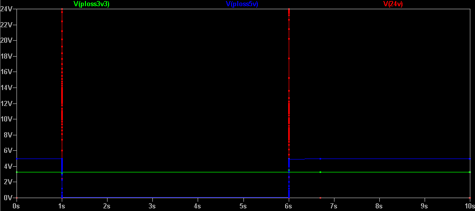
Tracing the voltages, it's not even giving the 1.3 volts that I measure on the "real thing" :
image

Now, maybe the library that I found is bogus, but maybe I also forgot something here. 

One thing that I noticed is that the LTSpice symbol is not showing the "parasitic" diode on the N channel mosfet, while the application note clearly says that it's integral to the behavior of this arrangement.

Adding a single diode across the S and D makes the levels work properly, but then I figured that I could go with just a Schottky diode as I'm only ever interested in the 5V side pulling down the 3.3V side, not the other way around. A simple 1N5819 being enough, I'm all sorted, but I'm posting here in the hope of learning what I missed both in the simulation and the real life arrangement.

  • Sign in to reply
  • Cancel

Top Replies

  • michaelkellett
    michaelkellett 1 month ago +3
    I rather think that there may be an error in your model. I re-did from scratch and seen no problem. I used BSS123 which is in the LT Spice library. MK
  • michaelkellett
    michaelkellett 1 month ago in reply to obones +3
    I tried it like this: MK
  • shabaz
    shabaz 1 month ago in reply to obones +3
    Hi, SOT-23 are actually quite massive if you've not encountered them before, they are about the length of a small through-hole 1/8W resistor, and the pins are spaced quite far apart, see the photo below…
Parents
  • shabaz
    0 shabaz 1 month ago

    This is quite tricky to follow because the earlier question links to another earlier question, so it's a chain of three discussions to try to understand the purpose. It maybe needs a diagram of your proposed solution in context of your entire system.

    Anyway, regarding the level conversion, I didn't understand the circuit, however I was more concerned that you mentioned that the Orange Pi crashed. That's worrying, and makes me wonder if some of the electrical signals or levels are not as expected, or if power is reaching devices through (say) GPIO when there is no power applied to the device, causing unexpected behaviour.

    In theory, you could just use some resistors to reduce the voltage levels (i.e. potential divider), e.g. use three resistors chained into a potential divider if you need separate outputs for 3.3V and 5V logic. But I'm not sure I'd do that if it were me. I think (since I don't understand the 24V source signal origin, and if it's really 24V, or has the capability to vary - by the way, make sure to configure the PIC input as a Schmitt trigger input) I'd rather use some additional circuitry, and it may as well be an optocoupler, just to completely isolate things. They are cheap.

    Secondly, I feel uncomfortable with the idea of connecting that signal to both the Pi and the PIC chip, because what's the device that's supposed to be in control and co-ordinate things? I think that device is supposed to be the PIC chip, acting as a sort of power management device, therefore, why not give it control of passing signals to the Pi as required. In other words, only translate the 24V signal to be used by the PIC, and the PIC can use GPIO to send a signal to the Pi as required. That way, the PIC is always in control, and won't pass on any input signal glitches to the Pi. It just seems more structured this way (but I don't know the detail).

    Thirdly, can the PIC run from 3.3V instead? That way, there's no need to worry about level translations between PIC and Pi at least (but if you do need to interwork 5V and 3.3V logic there in the PIC to Pi direction, then you can just use two resistors as a potential divider at that interface between PIC and PI).

    • Cancel
    • Vote Up 0 Vote Down
    • Sign in to reply
    • Verify Answer
    • Cancel
  • obones
    0 obones 1 month ago in reply to shabaz

    Thanks for your interest and sorry for the "chain" of messages, I didn't want to start with a too long explanation as the issue here came up from my project but could also apply to others.
    Basically, I have a 24V power source that may disappear so I need a signal to tell me so. In the very first discussion, I came up with a 2N3904 which base is controlled by that 24V signal and whose collector is simply pulling down to 0V when the 24V is there. With the appropriate 3.3V pull up, I then got a signal that tells me when 24V is there (0) or when it has gone (1) and thus have the OrangePi react to the power being gone by properly shutting down while 5V capacitors are being slowly emptied.
    Sadly, this was not enough because OrangePI needs to be fully disconnected for it to properly restart after shutdown, and so the subject of my second message was to find a way to have a more complex set of signals to control this.
    Using a PIC16F628 that was lying around, I was able to write the proper control program, but because that PIC uses 5V power, the OrangePI is on 3.3V, and both need the "24V is gone" signal, hence my need for a "level shifter"

    That final need led me to the research here, with the application note I mentioned and the puzzling fact that it appears not to work. As dang74 said, I was able to get a working situation with a simple 1N5819 diode but there is this part of my mind that wonders why the setup from the application note failed in real life and even does not simulate properly at all in LTSpice.

    • Cancel
    • Vote Up 0 Vote Down
    • Sign in to reply
    • Verify Answer
    • Cancel
  • shabaz
    0 shabaz 1 month ago in reply to obones

    This is the problem with these types of circuits; they're always 'on the edge', requiring one to hope that 3.3V really is 3.3V and not (say) 3.1V, and that the MOSFET can switch on sufficiently (and that's not even considering that there will be a further 0.2V or so across the BJT, could be replaced with another MOSFET but it's still ugly).. It's just not needed when there are better ways to do things that are not so critical of components and voltages. Sometimes worth re-thinking bits of the solution, rather than (say) just use a 5V microcontroller if it can run at 3.3V.

    BSS88 is ancient/obsolete, so if you have these, are they from Amazon/AliExpress? In which case, they may be something completely different but deliberately marked wrong. That could explain why your real-life circuit doesn't pull as low as desired.

    You could try a different low Vgs MOSFET that isn't obsolete, e.g. BSS138 is a reasonably choice, and plenty in stock at Farnell etc. 

    Regarding the different results with LTspice, it may indeed be an issue with the model or how it was pulled in. Might be worth trying a different model if LTspice has any built-in with low Vgs, otherwise googling 'BSS138 spice' there was a downloadable model from one of the manufacturers online.

    • Cancel
    • Vote Up +2 Vote Down
    • Sign in to reply
    • Verify Answer
    • Cancel
  • obones
    0 obones 1 month ago in reply to shabaz

    Thanks for your suggestion about ancient stock, I know that the BSS88 is obsolete and before using it, I looked for a T092 replacement, but could not find any. BSS138 would I believe be fine, but being an SMD component makes it harder for me to use it, hence the reason why I did not look for it.

    • Cancel
    • Vote Up 0 Vote Down
    • Sign in to reply
    • Verify Answer
    • Cancel
Reply
  • obones
    0 obones 1 month ago in reply to shabaz

    Thanks for your suggestion about ancient stock, I know that the BSS88 is obsolete and before using it, I looked for a T092 replacement, but could not find any. BSS138 would I believe be fine, but being an SMD component makes it harder for me to use it, hence the reason why I did not look for it.

    • Cancel
    • Vote Up 0 Vote Down
    • Sign in to reply
    • Verify Answer
    • Cancel
Children
  • shabaz
    0 shabaz 1 month ago in reply to obones

    Hi, SOT-23 are actually quite massive if you've not encountered them before, they are about the length of a small through-hole 1/8W resistor, and the pins are spaced quite far apart, see the photo below for a comparison of SOT-23 along with the tweezers that can easily grip them.

    image

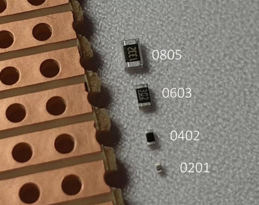
    SOT-23 will easily fit on the underside of stripboard (make a cut on a track, and then solder the SOT-23 onto the two cut ends and the next track). The photo below shows that you can also use 0805 resistors very easily with stripboard too (and also 0603 is very easy too. 0402 is definitely not advisable for this type of prototyping. 

    image

    The BSS123 that michaelkellett demonstrated is available in a SOT-23 option, and it's probably the most popular MOSFET for prototyping (way more popular than TO92 these days). 

    Your TO92 BSS88 would have worked, except it's very likely a fake part. Definitely recommended not to buy any of these types of semiconductor parts from AliExpress/Amazon, any SOT-23 BSS123 from there will likely be fake too, and would exhibit the same issue most likely.

    • Cancel
    • Vote Up +3 Vote Down
    • Sign in to reply
    • Verify Answer
    • Cancel
element14 Community

element14 is the first online community specifically for engineers. Connect with your peers and get expert answers to your questions.

  • Members
  • Learn
  • Technologies
  • Challenges & Projects
  • Products
  • Store
  • About Us
  • Feedback & Support
  • FAQs
  • Terms of Use
  • Privacy Policy
  • Legal and Copyright Notices
  • Sitemap
  • Cookies

An Avnet Company © 2025 Premier Farnell Limited. All Rights Reserved.

Premier Farnell Ltd, registered in England and Wales (no 00876412), registered office: Farnell House, Forge Lane, Leeds LS12 2NE.

ICP 备案号 10220084.

Follow element14

  • X
  • Facebook
  • linkedin
  • YouTube