element14 Community
element14 Community
    Register Log In
  • Site
  • Search
  • Log In Register
  • Community Hub
    Community Hub
    • What's New on element14
    • Feedback and Support
    • Benefits of Membership
    • Personal Blogs
    • Members Area
    • Achievement Levels
  • Learn
    Learn
    • Ask an Expert
    • eBooks
    • element14 presents
    • Learning Center
    • Tech Spotlight
    • STEM Academy
    • Webinars, Training and Events
    • Learning Groups
  • Technologies
    Technologies
    • 3D Printing
    • FPGA
    • Industrial Automation
    • Internet of Things
    • Power & Energy
    • Sensors
    • Technology Groups
  • Challenges & Projects
    Challenges & Projects
    • Design Challenges
    • element14 presents Projects
    • Project14
    • Arduino Projects
    • Raspberry Pi Projects
    • Project Groups
  • Products
    Products
    • Arduino
    • Avnet Boards Community
    • Dev Tools
    • Manufacturers
    • Multicomp Pro
    • Product Groups
    • Raspberry Pi
    • RoadTests & Reviews
  • Store
    Store
    • Visit Your Store
    • Choose another store...
      • Europe
      •  Austria (German)
      •  Belgium (Dutch, French)
      •  Bulgaria (Bulgarian)
      •  Czech Republic (Czech)
      •  Denmark (Danish)
      •  Estonia (Estonian)
      •  Finland (Finnish)
      •  France (French)
      •  Germany (German)
      •  Hungary (Hungarian)
      •  Ireland
      •  Israel
      •  Italy (Italian)
      •  Latvia (Latvian)
      •  
      •  Lithuania (Lithuanian)
      •  Netherlands (Dutch)
      •  Norway (Norwegian)
      •  Poland (Polish)
      •  Portugal (Portuguese)
      •  Romania (Romanian)
      •  Russia (Russian)
      •  Slovakia (Slovak)
      •  Slovenia (Slovenian)
      •  Spain (Spanish)
      •  Sweden (Swedish)
      •  Switzerland(German, French)
      •  Turkey (Turkish)
      •  United Kingdom
      • Asia Pacific
      •  Australia
      •  China
      •  Hong Kong
      •  India
      •  Korea (Korean)
      •  Malaysia
      •  New Zealand
      •  Philippines
      •  Singapore
      •  Taiwan
      •  Thailand (Thai)
      • Americas
      •  Brazil (Portuguese)
      •  Canada
      •  Mexico (Spanish)
      •  United States
      Can't find the country/region you're looking for? Visit our export site or find a local distributor.
  • Translate
  • Profile
  • Settings
Experts, Learning and Guidance
  • Technologies
  • More
Experts, Learning and Guidance
Ask an Expert Forum Single Mosfet level shifter does not appear to work
  • Blog
  • Forum
  • Documents
  • Leaderboard
  • Files
  • Members
  • Mentions
  • Sub-Groups
  • Tags
  • More
  • Cancel
  • New
Join Experts, Learning and Guidance to participate - click to join for free!
Actions
  • Share
  • More
  • Cancel
Forum Thread Details
  • State Not Answered
  • Replies 32 replies
  • Subscribers 268 subscribers
  • Views 1369 views
  • Users 0 members are here
Related
See a helpful answer?

Be sure to click 'more' and select 'suggest as answer'!

If you're the thread creator, be sure to click 'more' then 'Verify as Answer'!

Single Mosfet level shifter does not appear to work

obones
obones 1 month ago

Hello,

As a follow-up to my previous question, I have written a little program for the PIC16F628A that I had been lying around for quite a while. It works well, but I have to make sure the "PowerLoss" signal is seen by both the PIC and the OrangePi.
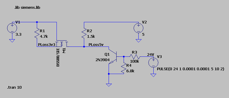
As the PIC works at 5V and the Orange Pi at 3.3V without being 5V tolerant, I have to shift the levels between both sides. After looking around, I found the AN97055 application note from Philips that mentions a single NMOS level shifter and even recommends using a BSS88 that I also had around.

However, after having wired it in a way that I believe is right, I noticed that when PowerLoss "pulls down" the 5V side, the 3.3V side is not event close to zero volts, but rather around 1.3 volts. This is not liked by the H3 inside the OrangePi as it freezes itself after a while and I have to reboot it.

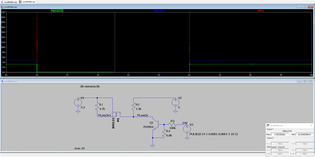
I tried to simulate the circuit with LTSpice and while it does not have the BSS88 by default, I found a library for it in the Blackboard project at github and so was able to create the following simulation:

image

Version 4
SHEET 1 1572 680
WIRE -128 0 -288 0
WIRE 0 0 -128 0
WIRE 528 0 176 0
WIRE -128 32 -128 0
WIRE 176 32 176 0
WIRE -288 112 -288 80
WIRE 0 112 0 0
WIRE 528 112 528 80
WIRE -128 160 -128 112
WIRE -64 160 -128 160
WIRE -16 160 -64 160
WIRE 176 160 176 112
WIRE 176 160 80 160
WIRE 256 160 176 160
WIRE 336 160 256 160
WIRE 336 176 336 160
WIRE 432 224 400 224
WIRE 464 224 432 224
WIRE 608 224 544 224
WIRE 624 224 608 224
WIRE 432 256 432 224
WIRE 336 336 336 272
WIRE 432 336 336 336
WIRE 624 336 624 304
WIRE 336 400 336 336
FLAG 336 400 0
FLAG -288 112 0
FLAG 528 112 0
FLAG 624 336 0
FLAG -64 160 PLoss3v3
FLAG 256 160 PLoss5v
FLAG 608 224 24V
SYMBOL voltage -288 -16 R0
WINDOW 123 0 0 Left 0
WINDOW 39 0 0 Left 0
SYMATTR InstName V1
SYMATTR Value 3.3
SYMBOL voltage 528 -16 R0
WINDOW 123 0 0 Left 0
WINDOW 39 0 0 Left 0
SYMATTR InstName V2
SYMATTR Value 5
SYMBOL voltage 624 208 R0
WINDOW 123 0 0 Left 0
WINDOW 39 0 0 Left 0
SYMATTR InstName V3
SYMATTR Value PULSE(0 24 1 0.0001 0.0001 5 10 2)
SYMBOL npn 400 176 M0
SYMATTR InstName Q1
SYMATTR Value 2N3904
SYMBOL res -144 16 R0
SYMATTR InstName R1
SYMATTR Value 4.7k
SYMBOL res 160 16 R0
SYMATTR InstName R2
SYMATTR Value 1.5k
SYMBOL res 560 208 R90
WINDOW 0 0 56 VBottom 2
WINDOW 3 32 56 VTop 2
SYMATTR InstName R3
SYMATTR Value 100k
SYMBOL res 416 240 R0
SYMATTR InstName R4
SYMATTR Value 6.8k
SYMBOL nmos 80 112 R90
SYMATTR InstName M1
SYMATTR Value BSS88/SIE
SYMATTR Prefix X
TEXT -320 424 Left 2 !.tran 10
TEXT -272 -96 Left 2 !.lib siemens.lib

Tracing the voltages, it's not even giving the 1.3 volts that I measure on the "real thing" :

image

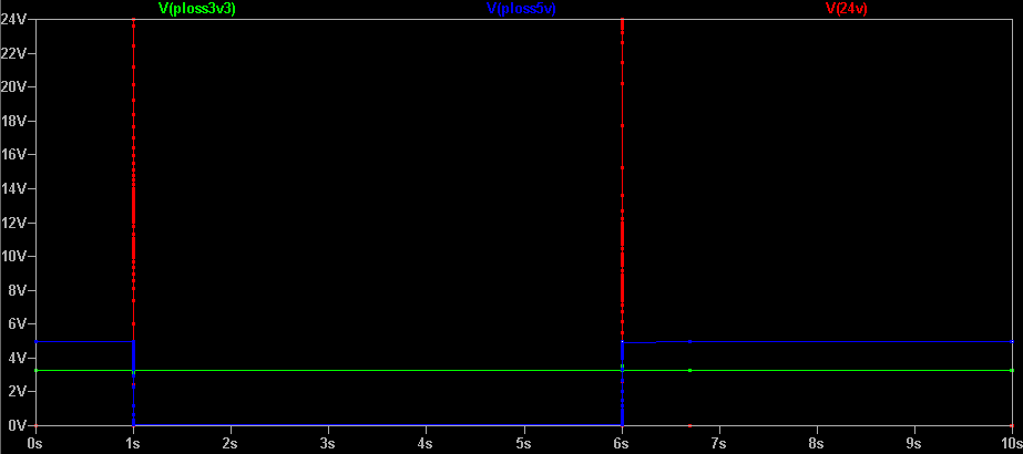
Now, maybe the library that I found is bogus, but maybe I also forgot something here. 

One thing that I noticed is that the LTSpice symbol is not showing the "parasitic" diode on the N channel mosfet, while the application note clearly says that it's integral to the behavior of this arrangement.

Adding a single diode across the S and D makes the levels work properly, but then I figured that I could go with just a Schottky diode as I'm only ever interested in the 5V side pulling down the 3.3V side, not the other way around. A simple 1N5819 being enough, I'm all sorted, but I'm posting here in the hope of learning what I missed both in the simulation and the real life arrangement.

  • Sign in to reply
  • Cancel

Top Replies

  • michaelkellett
    michaelkellett 1 month ago +3
    I rather think that there may be an error in your model. I re-did from scratch and seen no problem. I used BSS123 which is in the LT Spice library. MK
  • michaelkellett
    michaelkellett 1 month ago in reply to obones +3
    I tried it like this: MK
  • shabaz
    shabaz 1 month ago in reply to obones +3
    Hi, SOT-23 are actually quite massive if you've not encountered them before, they are about the length of a small through-hole 1/8W resistor, and the pins are spaced quite far apart, see the photo below…
Parents
  • michaelkellett
    0 michaelkellett 1 month ago

    I rather think that there may be an error in your model.

    I re-did from scratch and seen no problem.

    I used BSS123 which is in the LT Spice library.

    image

    MK

    • Cancel
    • Vote Up +3 Vote Down
    • Sign in to reply
    • Verify Answer
    • Cancel
  • dang74
    0 dang74 1 month ago in reply to michaelkellett

    What happens if you ditch Q2, R4 and V4 to bring the circuit more in line with that of obones?

    • Cancel
    • Vote Up 0 Vote Down
    • Sign in to reply
    • Verify Answer
    • Cancel
  • obones
    0 obones 1 month ago in reply to dang74

    I just tried it, it works as expected
    image

    • Cancel
    • Vote Up 0 Vote Down
    • Sign in to reply
    • Verify Answer
    • Cancel
Reply
  • obones
    0 obones 1 month ago in reply to dang74

    I just tried it, it works as expected
    image

    • Cancel
    • Vote Up 0 Vote Down
    • Sign in to reply
    • Verify Answer
    • Cancel
Children
  • michaelkellett
    0 michaelkellett 1 month ago in reply to obones

    I tried it like this:

    image

    MK

    • Cancel
    • Vote Up +3 Vote Down
    • Sign in to reply
    • Verify Answer
    • Cancel
  • dang74
    0 dang74 1 month ago in reply to obones

    Nice... so it's either the model like Michael surmised... or it could be that there is something quirky about the BSS88 that doesn't make it work well in the simulation or real life.

    • Cancel
    • Vote Up 0 Vote Down
    • Sign in to reply
    • Verify Answer
    • Cancel
element14 Community

element14 is the first online community specifically for engineers. Connect with your peers and get expert answers to your questions.

  • Members
  • Learn
  • Technologies
  • Challenges & Projects
  • Products
  • Store
  • About Us
  • Feedback & Support
  • FAQs
  • Terms of Use
  • Privacy Policy
  • Legal and Copyright Notices
  • Sitemap
  • Cookies

An Avnet Company © 2025 Premier Farnell Limited. All Rights Reserved.

Premier Farnell Ltd, registered in England and Wales (no 00876412), registered office: Farnell House, Forge Lane, Leeds LS12 2NE.

ICP 备案号 10220084.

Follow element14

  • X
  • Facebook
  • linkedin
  • YouTube