I'm in need of an analog circuit that can generate a square wave output of 20MHz. My first thought was to use a schmitt trigger inverter with a crystal, but then I thought of using a fast opamp to make it more challenging and a fun to work on project.
I came across this circuit made using LT1712 4.5ns comparator from Linear Technologies (now ADI). The circuit below generates a square wave output with a freq. of 1MHz which is filtered to obtain a sine wave of 1MHz. It uses a series resonant crystal to generate a stable 1MHz signal as shown in Fig.1
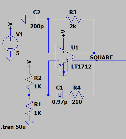
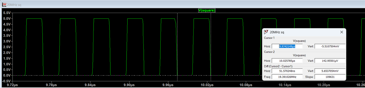
I modified the circuit, by replacing the crystal with a 20MHz one and R3, C1 by using another circuit given in the datasheet of LT1016 for 10MHz to 25MHz signal as shown in Fig. 2. I made a PCB to test the chip. However, my output frequency is around 10MHz with a distorted square wave output. I have tried the circuit in LTspice where it gives proper 20MHz output.
Hence, I need help in understanding how the series resonant crystal circuit is working, why the 210 ohm resistor? and how the R3 and C1affect the output freq? As the values are both different in the two circuit diagrams. I have also posted the LTspice circuit simulation and output as well as the measured output of my PCB.
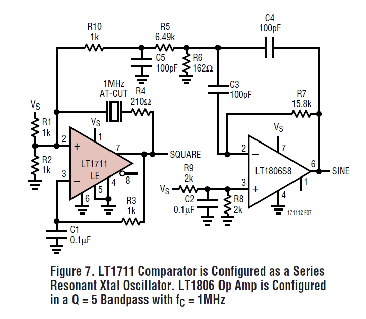
Fig. 1: LT1017 1MHz square wave gen
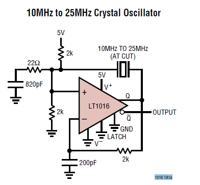
Fig.2: LT1016 10MHz to 25 MHz generator
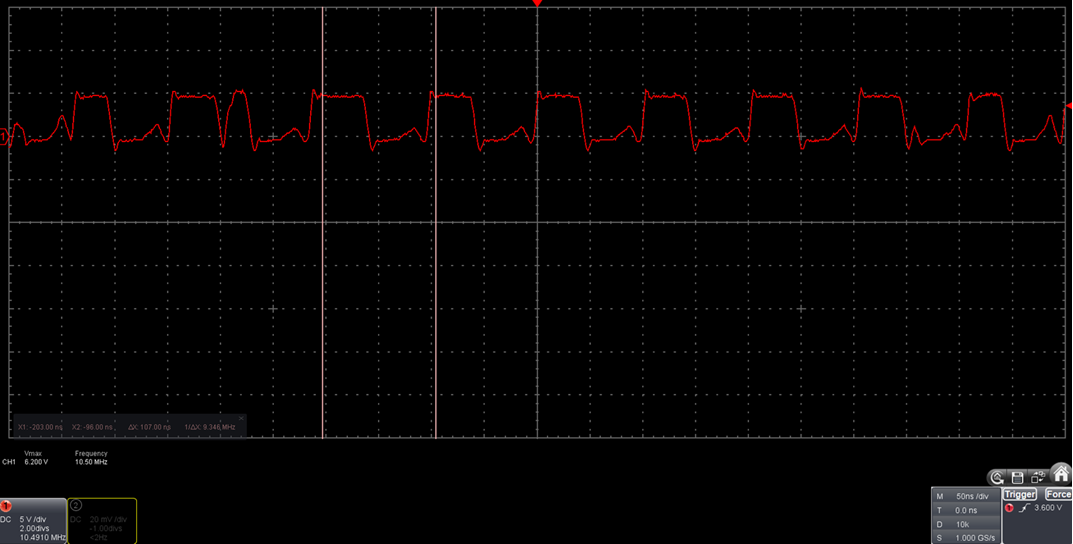
DSO output