element14 Community
element14 Community
    Register Log In
  • Site
  • Search
  • Log In Register
  • About Us
  • Community Hub
    Community Hub
    • What's New on element14
    • Feedback and Support
    • Benefits of Membership
    • Personal Blogs
    • Members Area
    • Achievement Levels
  • Learn
    Learn
    • Ask an Expert
    • eBooks
    • element14 presents
    • Learning Center
    • Tech Spotlight
    • STEM Academy
    • Webinars, Training and Events
    • Learning Groups
  • Technologies
    Technologies
    • 3D Printing
    • FPGA
    • Industrial Automation
    • Internet of Things
    • Power & Energy
    • Sensors
    • Technology Groups
  • Challenges & Projects
    Challenges & Projects
    • Design Challenges
    • element14 presents Projects
    • Project14
    • Arduino Projects
    • Raspberry Pi Projects
    • Project Groups
  • Products
    Products
    • Arduino
    • Avnet Boards Community
    • Dev Tools
    • Manufacturers
    • Multicomp Pro
    • Product Groups
    • Raspberry Pi
    • RoadTests & Reviews
  • Store
    Store
    • Visit Your Store
    • Choose another store...
      • Europe
      •  Austria (German)
      •  Belgium (Dutch, French)
      •  Bulgaria (Bulgarian)
      •  Czech Republic (Czech)
      •  Denmark (Danish)
      •  Estonia (Estonian)
      •  Finland (Finnish)
      •  France (French)
      •  Germany (German)
      •  Hungary (Hungarian)
      •  Ireland
      •  Israel
      •  Italy (Italian)
      •  Latvia (Latvian)
      •  
      •  Lithuania (Lithuanian)
      •  Netherlands (Dutch)
      •  Norway (Norwegian)
      •  Poland (Polish)
      •  Portugal (Portuguese)
      •  Romania (Romanian)
      •  Russia (Russian)
      •  Slovakia (Slovak)
      •  Slovenia (Slovenian)
      •  Spain (Spanish)
      •  Sweden (Swedish)
      •  Switzerland(German, French)
      •  Turkey (Turkish)
      •  United Kingdom
      • Asia Pacific
      •  Australia
      •  China
      •  Hong Kong
      •  India
      •  Korea (Korean)
      •  Malaysia
      •  New Zealand
      •  Philippines
      •  Singapore
      •  Taiwan
      •  Thailand (Thai)
      • Americas
      •  Brazil (Portuguese)
      •  Canada
      •  Mexico (Spanish)
      •  United States
      Can't find the country/region you're looking for? Visit our export site or find a local distributor.
  • Translate
  • Profile
  • Settings
Internet of Things
  • Technologies
  • More
Internet of Things
Forum Resistor rating for IR LED for WiFi IoT remote
  • Blog
  • Forum
  • Documents
  • Quiz
  • Events
  • Polls
  • Members
  • Mentions
  • Sub-Groups
  • Tags
  • More
  • Cancel
  • New
Join Internet of Things to participate - click to join for free!
Actions
  • Share
  • More
  • Cancel
Forum Thread Details
  • State Not Answered
  • Replies 16 replies
  • Subscribers 497 subscribers
  • Views 6805 views
  • Users 0 members are here
  • current
  • led
  • ir
  • iot
  • resistor
  • remote
Related

Resistor rating for IR LED for WiFi IoT remote

ntewinkel
ntewinkel over 3 years ago

Hello!

I was pondering this, and searching into the webs and on the lines, and then realized I have this awesome community of smart people here that probably already know the answers!

Short version:
Are 1/4 watt resistors enough to pulse an LED at 1 amp for an IR remote?
The LED is rated for 100mA continuous, 1.5 amp peak, and 1.6v forward voltage max.
I used an online calculator to figure out that with a 5v supply, a 6.8 ohm resistor will give it a 500mA current, and 3.4 ohms gives a 1amp current.

I'm not sure how to calculate the current on that LED - is it 1.6 volts x 1 amp? or 5 volts x 1 amp?

Either way though - even just the 1.6 watts is 6 times the current rating of the resistors I have. Is that ok for pulsed use for remote control like that?

Should I be using a set of parallel resistors instead (knowing I'll have to up the resistor values to compensate) ?

Project details:
My heat pump is kinda noisy, so at night we set it to "night mode" which is the quietest fan setting it has. We can't keep it at that setting because it won't heat the house well enough, so in the morning we turn the temperature up a few degrees and set the fan to "automatic".

I've been trying to automate this process, because the heat pump remote is kind of annoying in that you have to step through all 5 fan speeds to get back to Automatic.

I bought a little WiFi IR remote off Amazon a few years ago, which is ok for turning the heat up in the morning, but it only supports 3 basic fan speeds, so it doesn't properly turn the fan down at night. I recently bought another similar newer unit, hoping that after a few years my Daikin heat pump would now be fully supported, but it's still the same. Frowning2

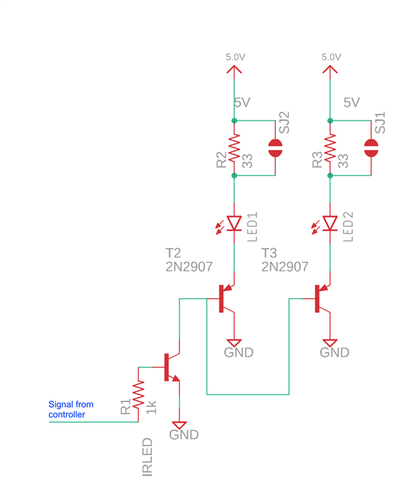
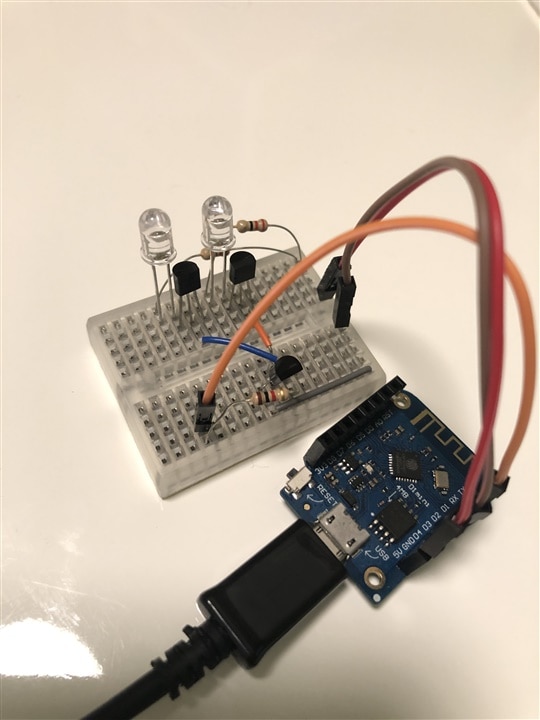
But there's hope! I found a Github repository that actually fully supports my Daikin heat pump codes! And for my favourite IoT micro-controller even - the Wemos D1 Mini.

Using a basic IR LED I had scavenged from something in the past, I was able to get it to work, but the IR LED range was just -barely- able to reach the heat pump when aimed just right (I realize now that I was using far to big a resistor value).

So I got a few new "high power" IR LEDs (the clear QED234 ones) from element14's shop, which I hope will give me the range I need. Then I did the aforementioned calculations to find the ideal resistor values to get some good oompf out of the LED to reach further.

I was just about to start soldering things up when I realized that 1amp of current is higher than the 1/4 watt rating of the resistors I have.

I'm hoping you'll have some good advice for this software-biased hobbyist Laughing

Also - I'm guessing a resistor failure would generally not cause a short? (ie, losing a resistor is ok, I have plenty more - losing an IR LED is tougher as I only have a few!)

Thanks!
-Nico

  • Sign in to reply
  • Cancel

Top Replies

  • ntewinkel
    ntewinkel over 3 years ago +6
    Hi All, It works! It seems I was overthinking things, as usual :D I just tested a 2-LED circuit using 22 ohm resistors, which runs the LEDs at about 150mA, and it seems to be plenty to reach the…
  • wolfgangfriedrich
    wolfgangfriedrich over 3 years ago +5
    Hello Nico, some comments: 1) Remotes usually send a modulated signal (38 kHz is a very common frequency, but anything between 34 and 56 kHz could be possible). This is good for your use case, as it…
  • fmilburn
    fmilburn over 3 years ago +3
    Hi Nico, It is easiest to look at the 1A case. There will be a 1A x 3.4R = 3.4v drop across the resistor and 1.6V drop across the LED. Since power = I*I*R the resistor sees spikes of 3.4W and the LED…
  • ntewinkel
    0 ntewinkel over 3 years ago

    Here's a bit more information:

    The github repository for the library I'm using to handle the remote control details for the heat pump are here: https://github.com/crankyoldgit/IRremoteESP8266

    I found a few places that discuss the protocol used for my heat pump, including this one: http://rdlab.cdmt.vn/project-2013/daikin-ir-protocol

    In summary, it appears to be 35 bytes sent, with (roughly) at most a 50% duty cycle, but it depends on the bits - if a bit is 0, the duty cycle is about 33%. So Wolfgang's assumption of a 50% duty cycle is a safe choice.
    The total signal time appears to be about 41 milliseconds if all bits are 1 (= 50% duty cycle). if the bits are 0 the time will be longer but the duty cycle will be lower.

    I should sign off for the night - tomorrow is chicken wrangling day. sigh. my life has gone weird LOL. they're not my chickens Smiley Chicken it's a small flock of 7 so hopefully we'll get their feet treated without too much drama Smiley

    Thanks,
    -Nico

    • Cancel
    • Vote Up +1 Vote Down
    • Sign in to reply
    • Verify Answer
    • Cancel
  • ntewinkel
    0 ntewinkel over 3 years ago

    Hi all,

    I just found some additional information on Adafruit that I think will clear up my resistor current worries.

    They are using a Raspberry Pi Zero with a QT-Py-Hat as a WiFi controlled IR remote control, which is exactly what I'm aiming for too, so I have hope it will also work in my setup.
    This is the Adafruit page with all the details: https://learn.adafruit.com/iot-ir-remote-using-raspberry-pi-zero-w-and-qtpy-hat/parts-required

    They recommend using 2 LEDs, where one is a wide angle LED and the other one a narrow angle LED. Each LED gets a transistor, which are both switched with a 3rd transistor that is controlled by the micro controller.

    The recommended IR LEDs are rated to 100mA with 1amp max, and 1.6v forward voltage. My LEDs have the same spec, with higher peak amps, so I assume they will behave in a similar way.

    For the resistors, they use ("optional") 33 ohm resistors, which if the online calculators are correct, comes out to the basic 100mA rating of the LED. Their explanation says these are optional and indicate they are only there to limit current if the LEDs draw so much power that they crash the main board. They are just using basic 1/4w resistors in that case too.

    They also have this IR-only project, using the same kind of circuit.
    https://learn.adafruit.com/building-an-infrared-transmitter-and-receiver-board
    The schematics for that are open source too: https://github.com/cyborg5/IRIO3 

    "The first option is to add a 33 ohm current limiting resistor in line with each of the LEDs. Without them, this circuit will drive the IR LEDs beyond their rated continuous current capacity. However because IR signals are intermittent and modulated it is safe to do this."

    This is a close-up of the schematic of the QT-Py-Hat on the Adafruit website, which has an IR transmitter on it. It's open source. (I've erased the bits that don't apply to my case).

    IR transmitter remote control circuit

    So, I'm guessing if they are leaving out the resistors altogether and aren't worried about burning the LEDs, then I probably don't need to worry about the resistor rating too much either, especially if I keep it within a reasonable range.

    -Nico

    • Cancel
    • Vote Up +1 Vote Down
    • Sign in to reply
    • Verify Answer
    • Cancel
  • ntewinkel
    0 ntewinkel over 3 years ago

    One more question...

    Is this safe math I have here?

    If I run the LEDs at 1amp, using a 3.4 ohm resistor (1/4 watt rating), the power is 3.4 watts.

    But the duty cycle while sending is about 50%, so that brings us to about 1.7 watts.

    That only runs for about 50 milliseconds.

    I can very easily limit the number of times the signal gets with a software delay.
    It makes sense to only allow one message per second, which cuts it down to 1/20th of the time. In actual use, I only expect it to send 2 packets a day (night mode and day mode).

    So if I limit sending to at most once per second, then the average power over that second is about 0.09 watts, or only about 1/3 of the rated 1/4watts the resistor can handle.

    Is it safe to assume power dissipation levelling over a 1 second period? I guess it only needs the first 1/3 second.

    ps, by "safe" I mean I'm more concerned over fire safety risk than about resistor failure.

    Thanks!
    -Nico

    • Cancel
    • Vote Up 0 Vote Down
    • Sign in to reply
    • Verify Answer
    • Cancel
  • Jan Cumps
    0 Jan Cumps over 3 years ago in reply to phoenixcomm

    If you lose a parallel resistor, the resistance goes up and the current down.

    How will that scenario lead to led burn-out?

    • Cancel
    • Vote Up +1 Vote Down
    • Sign in to reply
    • Verify Answer
    • Cancel
  • ntewinkel
    0 ntewinkel over 3 years ago

    Hi All,

    It works!

    It seems I was overthinking things, as usual :D

    I just tested a 2-LED circuit using 22 ohm resistors, which runs the LEDs at about 150mA, and it seems to be plenty to reach the heat pump.
    So my aiming for 1 amp was really just far more than is necessary. And that would also be over the rating of the transistors I'm using Smiley 
    I think the reason for it not working before might've been due to the way I was using the transistors - the proper circuit uses an extra transistor just to trigger the LED-powering transistors.

    The math:
    If we assume it's still a 1.6v voltage drop on the LED, then the voltage drop across the resistor is 3.4. 
    At 150mA x 3.4 volts x 50% duty cycle, we get about 0.25 watts, which is exactly the 1/4 watt rating of the resistors.
    Voltage drop at 150mA will be a little higher, and 50% duty cycle is a theoretical worst case which never happens (bits set to 1 have a longer pause), and there will always be pauses between transmissions much longer than the 50ms packets too.

    So I feel much better about the current running through the resistors now - it peaks close to the 1/4 watt rating but doesn't go over, so even accidental continuous transmission should not be an issue.

    Here is my cleaned up circuit, but instead of 33 ohms, I'm using 22.

    IR Transmitter Circuit 2 LEDs

    And here is a picture of it on a little breadboard, powered by a Wemos D1 Mini.

    IR Transmitter on breadboard

    Thanks again for all of the excellent advice!

    -Nico

    • Cancel
    • Vote Up +6 Vote Down
    • Sign in to reply
    • Verify Answer
    • Cancel
  • phoenixcomm
    0 phoenixcomm over 3 years ago in reply to ntewinkel

    I like the minimalist approaches. 

    • Cancel
    • Vote Up +2 Vote Down
    • Sign in to reply
    • Verify Answer
    • Cancel
<
element14 Community

element14 is the first online community specifically for engineers. Connect with your peers and get expert answers to your questions.

  • Members
  • Learn
  • Technologies
  • Challenges & Projects
  • Products
  • Store
  • About Us
  • Feedback & Support
  • FAQs
  • Terms of Use
  • Privacy Policy
  • Legal and Copyright Notices
  • Sitemap
  • Cookies

An Avnet Company © 2025 Premier Farnell Limited. All Rights Reserved.

Premier Farnell Ltd, registered in England and Wales (no 00876412), registered office: Farnell House, Forge Lane, Leeds LS12 2NE.

ICP 备案号 10220084.

Follow element14

  • X
  • Facebook
  • linkedin
  • YouTube