element14 Community
element14 Community
    Register Log In
  • Site
  • Search
  • Log In Register
  • About Us
  • Community Hub
    Community Hub
    • What's New on element14
    • Feedback and Support
    • Benefits of Membership
    • Personal Blogs
    • Members Area
    • Achievement Levels
  • Learn
    Learn
    • Ask an Expert
    • eBooks
    • element14 presents
    • Learning Center
    • Tech Spotlight
    • STEM Academy
    • Webinars, Training and Events
    • Learning Groups
  • Technologies
    Technologies
    • 3D Printing
    • FPGA
    • Industrial Automation
    • Internet of Things
    • Power & Energy
    • Sensors
    • Technology Groups
  • Challenges & Projects
    Challenges & Projects
    • Design Challenges
    • element14 presents Projects
    • Project14
    • Arduino Projects
    • Raspberry Pi Projects
    • Project Groups
  • Products
    Products
    • Arduino
    • Avnet Boards Community
    • Dev Tools
    • Manufacturers
    • Multicomp Pro
    • Product Groups
    • Raspberry Pi
    • RoadTests & Reviews
  • Store
    Store
    • Visit Your Store
    • Choose another store...
      • Europe
      •  Austria (German)
      •  Belgium (Dutch, French)
      •  Bulgaria (Bulgarian)
      •  Czech Republic (Czech)
      •  Denmark (Danish)
      •  Estonia (Estonian)
      •  Finland (Finnish)
      •  France (French)
      •  Germany (German)
      •  Hungary (Hungarian)
      •  Ireland
      •  Israel
      •  Italy (Italian)
      •  Latvia (Latvian)
      •  
      •  Lithuania (Lithuanian)
      •  Netherlands (Dutch)
      •  Norway (Norwegian)
      •  Poland (Polish)
      •  Portugal (Portuguese)
      •  Romania (Romanian)
      •  Russia (Russian)
      •  Slovakia (Slovak)
      •  Slovenia (Slovenian)
      •  Spain (Spanish)
      •  Sweden (Swedish)
      •  Switzerland(German, French)
      •  Turkey (Turkish)
      •  United Kingdom
      • Asia Pacific
      •  Australia
      •  China
      •  Hong Kong
      •  India
      •  Korea (Korean)
      •  Malaysia
      •  New Zealand
      •  Philippines
      •  Singapore
      •  Taiwan
      •  Thailand (Thai)
      • Americas
      •  Brazil (Portuguese)
      •  Canada
      •  Mexico (Spanish)
      •  United States
      Can't find the country/region you're looking for? Visit our export site or find a local distributor.
  • Translate
  • Profile
  • Settings
Motors and Drives
  • Technologies
  • More
Motors and Drives
Forum need help with a stepper driver
  • Blog
  • Forum
  • Documents
  • Events
  • Polls
  • Files
  • Members
  • Mentions
  • Sub-Groups
  • Tags
  • More
  • Cancel
  • New
Join Motors and Drives to participate - click to join for free!
Actions
  • Share
  • More
  • Cancel
Forum Thread Details
  • State Suggested Answer
  • Replies 18 replies
  • Answers 3 answers
  • Subscribers 75 subscribers
  • Views 3394 views
  • Users 0 members are here
  • help
  • stepper_motor
  • manual
  • motor_driveboard
  • instruction_manual
  • stepper_driver
  • motor_control_drive
  • instruction
  • help_required
  • division_setting_table
  • motor
  • arduino
  • motor_circuits
  • stepper_drive
Related

need help with a stepper driver

Former Member
Former Member over 12 years ago

imageimageimageimageimageimage

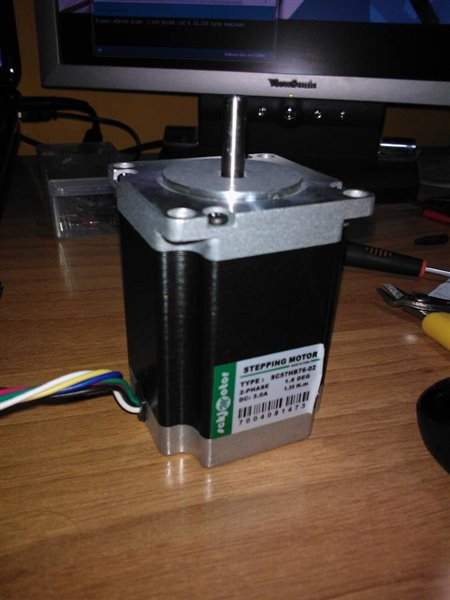
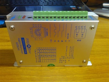
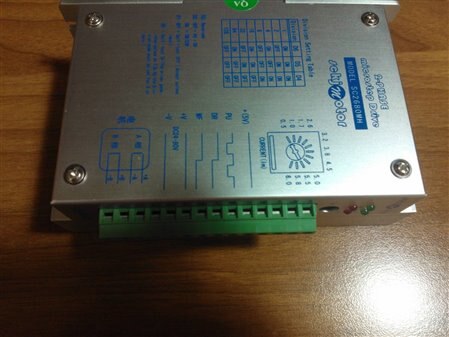
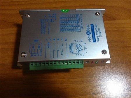
this is a 2-phase stepper motor drive by a chinese company called SCKJMOTOR with the model number SC2680MH

it can be found here in this link http://sckjmotor.com/prodetail.asp?cid=3&scid=6&id=67

i am not much experienced with electronics so i cant figure out how to use it with out an instruction manual and sadly the manual is in chinese image

so i thought maybe i can find some help here on element 14


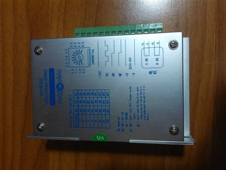
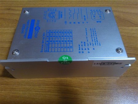
you can see in the pictures  the driver has lots off ports on it they go like  + , PU, + , DR, + , MF, + ,  TM, +V, -V, +A, -A, +B, -B


here i think the " + " ports might be a 5V input so i guess i must give 5V in them, but why are there so many???? why do i need to give the driver 5V at 4 different ports ???   image


the port " PU " might be pules, i am just guessing, it might be to control the speed of the motor  


the port " DR " maybe direction like forward-reverse, another guess 


the port " MF " i have no idea, cant even guess this one   image


the ports " +V " and " -V" the driver says on the side " DC24-80V "  so i guess i might have to give it some thing between 24V to 80V


the posts  +A, -A, +B, -B  are clear i guess, i just have to find the right coil pairs of the stepper motor and connect it to these ports  image 


there is also some thing called a division setting table and it gives me values  1, 2, 4, 8, 16, 32, 64 and 128 , i think this must be some thing related to the step divisions of the stepper motor, need some help with that as well


please try to help me out with this, i am just starting to take interset in electronice and dont have any experience in this at all, just have some basic electronic knowledge since i am doing engineering and its my 1st year


thank you

  • Sign in to reply
  • Cancel
Parents
  • bodgy
    0 bodgy over 12 years ago

    There are some Cantonese speaking people at work, but I'm on day off today, so it would be tomorrow before I could see if they would translate the datasheet for you.


    Looking at the wiring diagram from the link you posted.


    It does indeed look as though there are three + connections to 5v (perhaps there are 3 internal modules, I don't know). I thought MF might be the 'motor frame' connection, or to you and me, the ground/-v connection, on the other hand there is a timing diagram of a low to high pulse requiring 1uS rise time, so I'm not entirely sure. The wiring diagram has bracketed text underneath that wire, which normally means used or not used under certain conditions.


    As there is a timing diagram attached to the PU and DR, as you surmise the PU might well be the PWM drive pulse active on the high to low edge, my first thought was the same as you for DR, possible direction, but by the looks of the timing diagram it does something by going high to low 2.5uS whilst PU is high and before the PU pulses start, MF needs to be low to high before DR goes low.


    D4,5,6 switches are indeed the pulse step setting. D2 appears to change the way PU and DR relate to each other. D1 looks as though it might either change the PWM frequency or perhaps provides always on, always off and PWM modes of driving a motor. D3 haven't the faintest idea image .


    *******************************EDIT**************************************


    PU = PWM = motor speed.


    DR: Depends on setting of D2 , if D2 is ON it looks as though DR is the direction control by voltage, if D2 is OFF then it appears to require a pulse of some kind, without an actual translation that is just a guess.


    D3 is not used by this module currently.


    Colin


    Message was edited by: Colin Barnard   : Just looked at your images properly.

    • Cancel
    • Vote Up 0 Vote Down
    • Sign in to reply
    • Verify Answer
    • Cancel
  • Former Member
    0 Former Member over 12 years ago in reply to bodgy

    thank you very much for your help, appreciate it alot image

    please dont mind but i did not understand you completely because i have very less knowledge and experience, even my university professors are not very helpful with outside syllabus topics  image


    ok so what i understand from you is


    ill just give 5V in all the " + " ports 


    the PU ill just connect the microcontroller and make it give no off signals with 1uS delay depending on the speed i want 


    D1   says its for self test  when ON, i guess its just used to check if the motor is running and the connections are right 


    D2  says if  OFF = PU + DR    i still need little more detail info on DR  if its not direction then what is it exactly 

                  if  ON   = CW/CCW    i have no idea  image  whats CW whats CCW ???


    MF  , what is  motor frame ???

    • Cancel
    • Vote Up 0 Vote Down
    • Sign in to reply
    • Verify Answer
    • Cancel
Reply
  • Former Member
    0 Former Member over 12 years ago in reply to bodgy

    thank you very much for your help, appreciate it alot image

    please dont mind but i did not understand you completely because i have very less knowledge and experience, even my university professors are not very helpful with outside syllabus topics  image


    ok so what i understand from you is


    ill just give 5V in all the " + " ports 


    the PU ill just connect the microcontroller and make it give no off signals with 1uS delay depending on the speed i want 


    D1   says its for self test  when ON, i guess its just used to check if the motor is running and the connections are right 


    D2  says if  OFF = PU + DR    i still need little more detail info on DR  if its not direction then what is it exactly 

                  if  ON   = CW/CCW    i have no idea  image  whats CW whats CCW ???


    MF  , what is  motor frame ???

    • Cancel
    • Vote Up 0 Vote Down
    • Sign in to reply
    • Verify Answer
    • Cancel
Children
  • kas.lewis
    0 kas.lewis over 12 years ago in reply to Former Member

    I would input 5V to PU/DR+ and then connect the other connections as described (or how you understand them to be connected) and then just try diffrent things. I might suggest if you can get an O-scope or use one at the university that would give you better info then connecting to a motor at this point.


    And you do NOT need to connect MF to anything for now.

    • Cancel
    • Vote Up 0 Vote Down
    • Sign in to reply
    • Verify Answer
    • Reject Answer
    • Cancel
  • Former Member
    0 Former Member over 12 years ago in reply to kas.lewis

    there are four + ports so ill give 5V to all


    but PU and DR shouldnt they be connected to a mircocontroller ????? or any other controller


    ill ignore MF 


    and what about TM whats zero point, little more detail please is it some thing like reset or start position


    and the +V and -V  do i put like 24 V  there  its say DC24-80V    


    just trying to be safe, i hope i dont burn it 

    • Cancel
    • Vote Up 0 Vote Down
    • Sign in to reply
    • Verify Answer
    • Cancel
  • kas.lewis
    0 kas.lewis over 12 years ago in reply to Former Member

    I understand what you are saying about PU/DR, but from the schematic it looks like the pos are cennected  5V and neg to the controller (the controller could be used a s a pull down instead of a pull up, I am assuming). If you do this be sure the uC pins are rated at 5V.

    TM we could not fully understand but we understoof something about zero point, what that means we are unsure.


    +V and -V does look like it is connected to 24V


    Hope someone else can help explain teh setup, these are my assumtions from what I understood, maybe someone else can give some input as well.

    • Cancel
    • Vote Up 0 Vote Down
    • Sign in to reply
    • Verify Answer
    • Cancel
  • bodgy
    0 bodgy over 12 years ago in reply to Former Member

    CW = Clockwise.

    CCW = Counter Clockwise  or if you prefer anti clockwise.


    Will see what the Chinese people at work make of the datasheet.

    • Cancel
    • Vote Up 0 Vote Down
    • Sign in to reply
    • Verify Answer
    • Cancel
  • bodgy
    0 bodgy over 12 years ago in reply to bodgy

    OK, I have spoken to the Chinese gentleman at work, unfortunately his English is not brilliant, but I think the gist of what he said is -


    1. The datasheet is poorly written.


    2. If D2 is OFF,  step pulse signal is enabled.


    3. If D2 is ON direction control is enabled  - if it is low (0->0.5v direction is one way), if it is high (4-5v) the direction is the other.


    The pulse width on the DR must be 2.5uS wide.


    The input impedance of the DR line in the controller is 220 Ohms.


    So, my guess is that with D2 off, you cannot reverse the motor direction, it is clockwise only, D2 ON, allows motor direction change via the DR line.


    The 24-80v is the supply for your motor.


    The datasheet mentions the zero point but I'm told gives no further information other than the TM relates to it..


    Colin

    • Cancel
    • Vote Up 0 Vote Down
    • Sign in to reply
    • Verify Answer
    • Cancel
  • Former Member
    0 Former Member over 12 years ago in reply to bodgy

    i connected this motor to driver 

    image


    its a 6 wire stepper motor i found the +A -A +B -B wires and connected it to the driver in those ports 


    connected 24V to +V and -V


    first ran the motor in test mode which is D1 on, it runs fine when i keep the division table to 8 or higher ( as you can see in the driver pictures ) that is D6 off D5 off D4 on


    division table set to 8 the motor runs the fastest and runs slower as i go higher that is 16 32 64 128


    what is this division setting exactly  ???


    then i programed an arduino to give an pulse of width 1uS connected it to port PU and gave 5V in the first + port fron the top, it dint run then i gave 5V in the 2nd + port, the motor still does not run, i connected 5V to DR as well then the motor started running  but was very slow ( 1 rev in 6 secs) when the division setting is set to 8

    then i set the division setting to 1 that is D4 on D5 on D6 on , then the motor runs some what fast  ( 5 rotations in 1 sec ) ( D2 is on )

    • Cancel
    • Vote Up 0 Vote Down
    • Sign in to reply
    • Verify Answer
    • Cancel
  • manlong
    0 manlong over 11 years ago in reply to Former Member

    Hello,


    A stepper motor have has his name said a step. Generally  one step turn the rotor about 1.8° so to do a entire turn you have to send 200 pulse to PU.

    If you put a division, you reduce the angle. so divide by 2 one step will turn the rotor by 0.9° so you have to send 400 pulse to PU to do one rotation.

    What is the frequency of your pulse, you said a width of 1us but not the frequency.


    Syncerely

    Man Long

    • Cancel
    • Vote Up 0 Vote Down
    • Sign in to reply
    • Verify Answer
    • Cancel
  • Former Member
    0 Former Member over 11 years ago in reply to manlong

    hi,


    i am not sure about the frequency, what i am doing is, i connected the arduino to give the pulse and loaded the program of the blinking LED and changed the delay to 1uS between  the on and off signal

    • Cancel
    • Vote Up 0 Vote Down
    • Sign in to reply
    • Verify Answer
    • Cancel
  • manlong
    0 manlong over 11 years ago in reply to Former Member

    If you see the blinking led that the frequency is too low. You have to increase the frequency.

    If for example the frequency is 10Hz, the LED blink every 0.1s, to do 200 pulses you have to wait about 20 seconds. And this without division.

    So you have to increase your pulse frequency, the number of pulse within 1 second to rotate your motor fastly.

    The speed of the motor is the same as the speed you send your pulse.

    More you use division (1,2,4,8,...) more you will be precise but you have to send 1,2,4 times more to do 1 rotation


    Man Long

    • Cancel
    • Vote Up 0 Vote Down
    • Sign in to reply
    • Verify Answer
    • Cancel
  • Former Member
    0 Former Member over 11 years ago in reply to manlong

    i just realized a small mistake i was making in arduino program *facepalm* that i was taking to be microseconds was millisecond i was giving an on/off signal by the arduino with 1 millisecond delay in between [ delay(1) ], so i found an other command used for making delays in microsecond [ delayMicroseconds(500) ] so i changed the program a little and noticed that the max i can reduce it was 500 Microseconds

    now the on/off signal is with the delay of 500 Microseconds [ 1 sec = 100000 micro sec ]


    so now the motor is running almost 3 times faster  both forward and reverse


    one more thing, i have not made the arduinos and the drivers ground common, i have not used arduinos ground at all i have only taken the pulse from arduino and DR (direction) signal


    • Cancel
    • Vote Up 0 Vote Down
    • Sign in to reply
    • Verify Answer
    • Cancel
element14 Community

element14 is the first online community specifically for engineers. Connect with your peers and get expert answers to your questions.

  • Members
  • Learn
  • Technologies
  • Challenges & Projects
  • Products
  • Store
  • About Us
  • Feedback & Support
  • FAQs
  • Terms of Use
  • Privacy Policy
  • Legal and Copyright Notices
  • Sitemap
  • Cookies

An Avnet Company © 2025 Premier Farnell Limited. All Rights Reserved.

Premier Farnell Ltd, registered in England and Wales (no 00876412), registered office: Farnell House, Forge Lane, Leeds LS12 2NE.

ICP 备案号 10220084.

Follow element14

  • X
  • Facebook
  • linkedin
  • YouTube