element14 Community
element14 Community
    Register Log In
  • Site
  • Search
  • Log In Register
  • Community Hub
    Community Hub
    • What's New on element14
    • Feedback and Support
    • Benefits of Membership
    • Personal Blogs
    • Members Area
    • Achievement Levels
  • Learn
    Learn
    • Ask an Expert
    • eBooks
    • element14 presents
    • Learning Center
    • Tech Spotlight
    • STEM Academy
    • Webinars, Training and Events
    • Learning Groups
  • Technologies
    Technologies
    • 3D Printing
    • FPGA
    • Industrial Automation
    • Internet of Things
    • Power & Energy
    • Sensors
    • Technology Groups
  • Challenges & Projects
    Challenges & Projects
    • Design Challenges
    • element14 presents Projects
    • Project14
    • Arduino Projects
    • Raspberry Pi Projects
    • Project Groups
  • Products
    Products
    • Arduino
    • Avnet Boards Community
    • Dev Tools
    • Manufacturers
    • Multicomp Pro
    • Product Groups
    • Raspberry Pi
    • RoadTests & Reviews
  • Store
    Store
    • Visit Your Store
    • Choose another store...
      • Europe
      •  Austria (German)
      •  Belgium (Dutch, French)
      •  Bulgaria (Bulgarian)
      •  Czech Republic (Czech)
      •  Denmark (Danish)
      •  Estonia (Estonian)
      •  Finland (Finnish)
      •  France (French)
      •  Germany (German)
      •  Hungary (Hungarian)
      •  Ireland
      •  Israel
      •  Italy (Italian)
      •  Latvia (Latvian)
      •  
      •  Lithuania (Lithuanian)
      •  Netherlands (Dutch)
      •  Norway (Norwegian)
      •  Poland (Polish)
      •  Portugal (Portuguese)
      •  Romania (Romanian)
      •  Russia (Russian)
      •  Slovakia (Slovak)
      •  Slovenia (Slovenian)
      •  Spain (Spanish)
      •  Sweden (Swedish)
      •  Switzerland(German, French)
      •  Turkey (Turkish)
      •  United Kingdom
      • Asia Pacific
      •  Australia
      •  China
      •  Hong Kong
      •  India
      •  Korea (Korean)
      •  Malaysia
      •  New Zealand
      •  Philippines
      •  Singapore
      •  Taiwan
      •  Thailand (Thai)
      • Americas
      •  Brazil (Portuguese)
      •  Canada
      •  Mexico (Spanish)
      •  United States
      Can't find the country/region you're looking for? Visit our export site or find a local distributor.
  • Translate
  • Profile
  • Settings
Open Source Hardware
  • Technologies
  • More
Open Source Hardware
Blog Building a Dual Thermistor Air Temperature Sensor
  • Blog
  • Forum
  • Documents
  • Events
  • Polls
  • Members
  • Mentions
  • Sub-Groups
  • Tags
  • More
  • Cancel
  • New
Join Open Source Hardware to participate - click to join for free!
  • Share
  • More
  • Cancel
Group Actions
  • Group RSS
  • More
  • Cancel
Engagement
  • Author Author: shabaz
  • Date Created: 8 Feb 2020 5:15 PM Date Created
  • Views 4748 views
  • Likes 13 likes
  • Comments 8 comments
  • omega thermistor
  • thermistor
  • omega engineering
  • 44018 thermistor
  • temperature sensing
Related
Recommended

Building a Dual Thermistor Air Temperature Sensor

shabaz
shabaz
8 Feb 2020

  • Introduction
  • How does it work?
  • Building a Temperature Sensor
  • Summary


Introduction

This blog post describes a really simple (near-trivial) project – wiring up a thermistor!


Thermistors are great, but have a limited operational temperature range compared to (say) thermocouples. The aim was to use a thermistor for fast, accurate ambient temperature measurement because this is handy for checking the room for those who are slightly obsessive over their environmental temperature (i.e. me : ) or for recording the ambient conditions when performing an experiment. The final sensor is intended to provide +- 0.15 degree C accuracy in the room temperature range. image

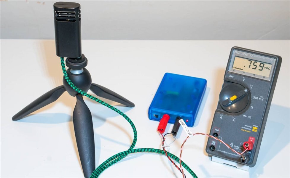
This photo shows the sensor in use; the measured voltage of 0.759V means a measured room temperature of (70.366 * 0.759) - 34.152 = 19.26 degrees C, where 70.366 and 34.152 are constants. This is explained in the text below.


The actual temperature of an object, or the perceived temperature for a person, isn’t solely related to the air temperature, but I figured it would be a starting point! The temperature of an object can differ from air temperature, depending on any radiant heat being absorbed, and how close the person or object is to another hot or cold entity – such as a cold wall nearby.


In theory all that is needed is a thermistor and a multimeter, and a table to refer to, to convert the measured resistance into a temperature value. Thermistors are non-linear so a table or the Steinhart-Hart formula is normally used. The resultant value based on the formula can be extremely accurate, in theory down to hundredths or even thousandths of a degree! (Note - ADC resolution matters! Even if [say] a 24-bit ADC is used, as will be seen below, the thermistor curve means that for part of the temperature range, the effective resolution can be far worse!).


In practice, I decided to use a ‘linear thermistor’, which is actually composed of two normal thermistors, arranged in such a way that when assembled into a potential divider circuit along with additional fixed resistors and a voltage source, the output takes on a straight line (y=mx+c from school-level lessons!) form instead of being a curve.


Nowadays it is far lower cost to just digitize a normal thermistor using an analog-to-digital converter (ADC) and then do the calculation in a microcontroller, however I wanted to try this linear thermistor for now until I eventually get around to such a project. I started a microcontroller-based thermistor project four years ago and got halfway through it. Building a Temperature Measurement System – Part 1  I hope to finish it one day.


So, this project is not necessarily a good solution nowadays, but it is a solution : ) Anyway, enough trashing of my own project : ) This solution provides an analog way of linearizing temperature measurements from non-linear sensors.


How does it work?

For the purpose of explanation, I will take a real thermistor model 10K3A1Bthermistor model 10K3A1B. This is not the one I used in the end, but it could be used, and it has a detailed datasheet.


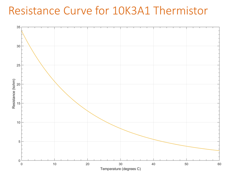
If a multimeter set to Ohms is connected across this thermistor, it can be observed that the measurement has a curve as shown here for the temperature range of 0 to 60 degrees C (it can operate beyond these temperatures, but this is the range I’m going to look at for now). You can see the thermistor response is definitely non-linear.

image


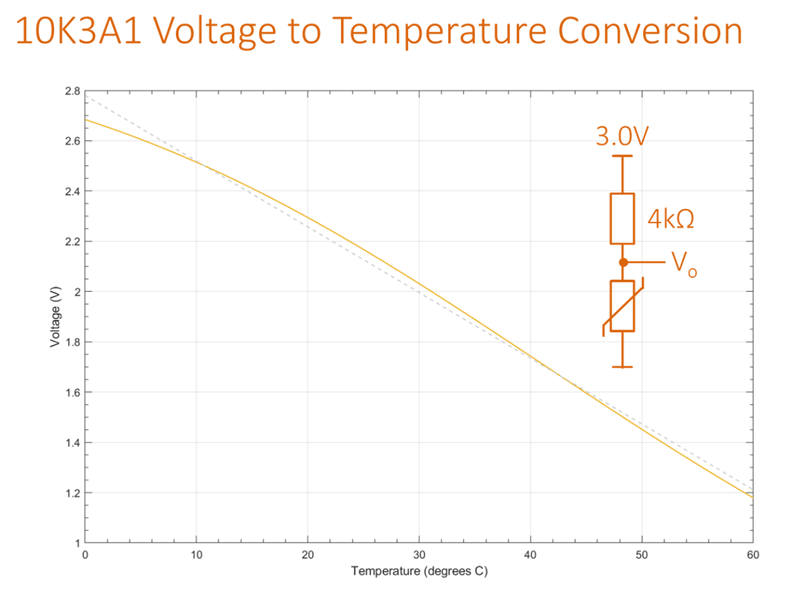
To measure the thermistor in a circuit rather than using an ohmmeter, ordinarily it is easier to measure a voltage, so it could be placed in series with a fixed resistance, so that a potential divider circuit is formed. For this example, the thermistor is connected to a 4 kohm fixed resistor, and 3.0V is applied to the circuit. Measuring across the thermistor would reveal the orange curve shown below. It is not straight. The dashed line is a straight line for comparison. The difference between the dashed straight line and the curve is as high as 3.5 degrees C at the low end. In other words, for the temperature range of 3.5 to 60 degrees C, if the measured voltage was assumed to have that straight line relationship to temperature, the error can be as high as 3.5 degrees C (not taking into account the tolerance of the components and the 3.0V supply and the temperature rise within the thermistor and resistor).

image


Next, a more complicated circuit was formed using two identical thermistors and an additional 10 kohm resistor.

Now if the voltage is measured, the output would look as shown on the blue curve below:

image


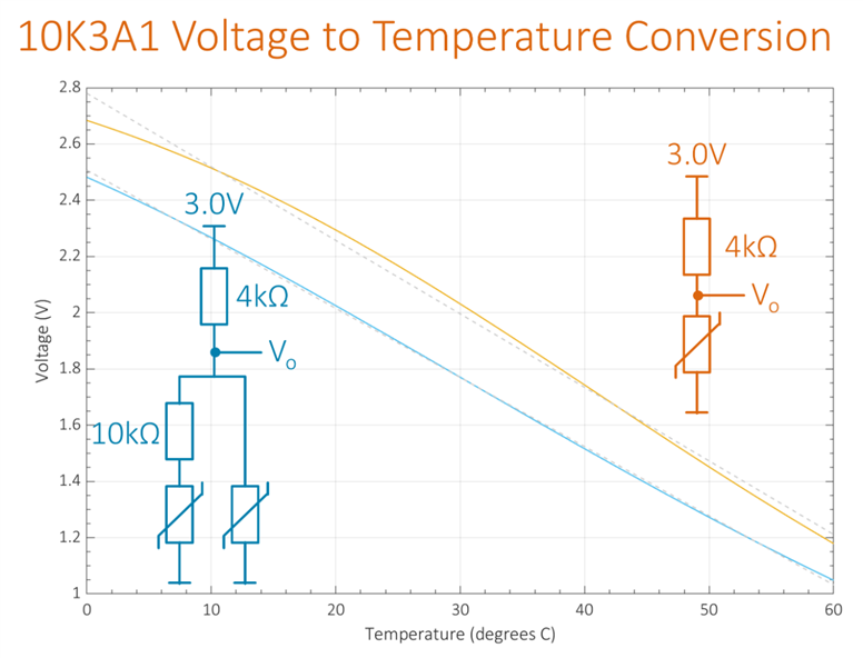
This is much better! Now the error for the range of 1 to 60 degrees C is no higher than 1 degree C, and in the room temperature range of 15-25 degrees C the error is no more than around 0.4 degrees C. So, to measure ambient temperature with a linear conversion from voltage to temperature, the dual thermistor solution could be an option.


Keeping the component values the same, if an overall reduced temperature range of just 10-50 degrees C was sufficient (and hopefully it should be, for room temperature), then it is possible to move the dashed straight line to hug the blue curve better in the 10-50 degree C range and that would reduce the linearity error to 0.27 degrees C maximum.


Incidentally the component values for the dual thermistor solution described above were arrived at by trial-and-error and are probably not optimal. There might be a formula-based procedure that could be written. Alternatively it would be straightforward to write a computer program to try hundreds or thousands of combinations and automatically determine the best one. But the above values might be ‘good enough’ depending on the application!


Building a Temperature Sensor

The solution described above relies on both thermistors being at the same temperature.


I was interested to try an integrated dual thermistor available from Omega, because the manufacturer has done the hard work of determining which two thermistors to integrate (they may be the same thermistor, or they may be of different composition; I’m unsure) and what resistor values to use. The manufacturer claims the solution is accurate to within +-0.15 degrees C and linear to within +- 0.065 degrees C, for the range of -5 to 45 degrees C. This is better than I achieved using trial-and-error, which is good news for the temperature-obsessed.


The dual thermistor comes with three leads, and it can be used in a circuit identical to the one shown earlier in blue, but with different values.

image


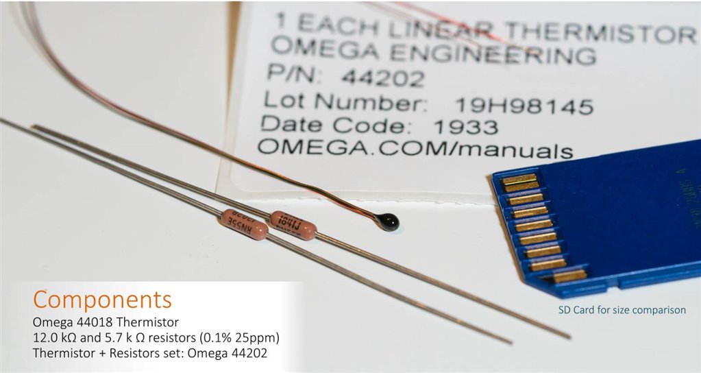
I followed the thermistor datasheet, and used a 12.0 kohm resistor for the lower leg of the circuit, and a 5.7 kohm resistor for the top of the potential divider. The thermistor is available in a kit with these resistors, but there’s no difference if the resistors are purchased separately provided they have a tight tolerance and low thermal change.

image

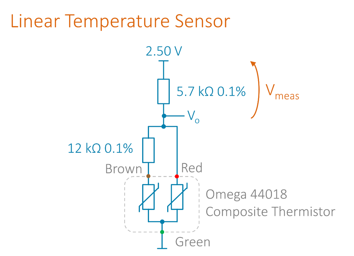
The voltage to measure, Vmeas is brought out to two twisted wires that can be connected to a voltmeter.


The wires were coiled rather than cut, so that when the ends were soldered, the thermal mass of the thermistor would still be low. I used a piece of wood sliced into a thin bridge as a support.

image

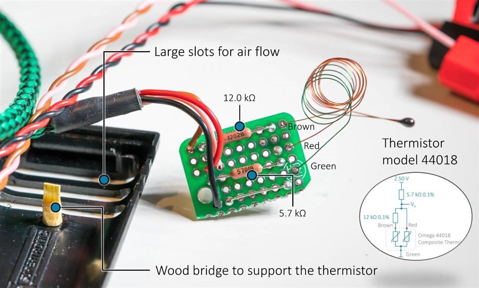
The enclosure has large holes for air flow. I epoxied the circuit board and cable in place, and used a tiny dab of epoxy to secure the thermistor to the wood bridge.

image

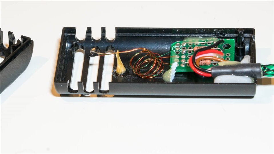
I glued in a camera tripod thread to allow me to position the sensor in a room at a repeatable position if desired.

image


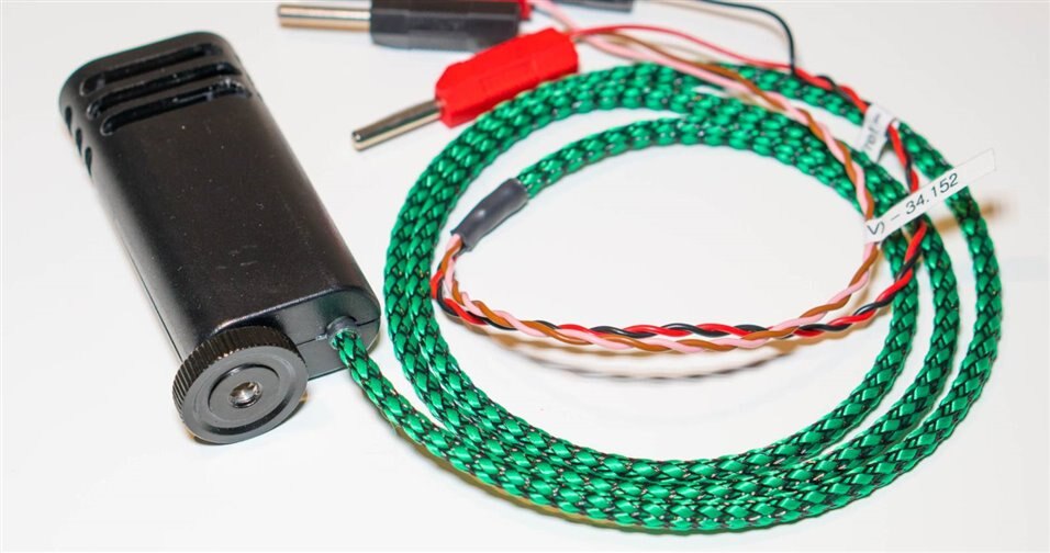
Finally, I labelled the wires with the linear formula so that I wouldn’t forget it!

For the Omega thermistor, the formula is:

Temperature (degrees C) = (70.366 * Vmeas) - 34.152

Where Vmeas is the measured voltage across the 5.7 kohm resistor when 2.50V is applied to the circuit.


The next question was, how to obtain the 2.50 volts! I built a small battery-powered reference for that. It contains a REF5025 REF5025 chip from Texas Instruments (I just followed the REF5025 PDF datasheet). I also placed a ready-made charger circuit inside, to reduce the reliance on Alkalines a little bit. The current consumption of the linear thermistor circuit is low and the small battery will last for several days of continuous measurements.

image


Summary

By using a linear thermistor composed of two integrated thermistors, it was possible to build an sensor device for room temperature measurement with (hopefully) high accuracy and precision. I have not been able to confirm the performance, but I believe it will be the most accurate sensor that I currently own for such measurements, which is not bad for the cost (the 44018 thermistor costs £22.50 plus tax and delivery).

Thanks for reading!

  • Sign in to reply

Top Comments

  • michaelkellett
    michaelkellett over 5 years ago +6
    Ah, a fine excuse to talk about my fridge controller. When I bought the fridge (at work) I used it to temperature test some weighing scales that were too big for my fancy env. chamber. It was controlled…
  • neuromodulator
    neuromodulator over 5 years ago +5
    Very nice! I'm doing something very similar to what you did in the first blog, which I just noticed now. I'm using a single unbranded thermistor which I first characterized its T/R curve using a lab mercury…
  • shabaz
    shabaz over 5 years ago in reply to michaelkellett +5
    Nice, project, it looks like you're easily getting 0.1 degree C resolution within the temperature range of interest, with the built-in ADC. The linear thermistor is £22.50+tax, so it's only suitable as…
  • shabaz
    shabaz over 5 years ago in reply to michaelkellett

    I got curious (at least as just a paper exercise, I didn't try to solder it up) to see a dual-thermistor attempt with low-cost thermistors!

    I have some AVX NB12SC0104JBBAVX NB12SC0104JBB which are 100k ohm 0805 sized parts and are 19 pence each. They have this resistance curve:

    image


    In theory, with the dual-thermistor topology, but with the top resistor being 47k and the lower resistor being 18k, and with a 3.3V supply, then this chart should apply:

    image

    The error due to the curve not being completely straight is less than 0.5 degrees C across almost the entire room-ish temperature range, but the error increases to just over 1 degrees C toward 0 degrees C.

    The gradient is about 37 mV per degree C, which is convenient for a microcontroller, because then an 8-bit ADC would provide a resolution of around 0.3 degrees C.

    The formula to calculate the temperature would be: T = 72.49 - (V * 26.78)


    Anyway, I guess it's not much use these days, since it is possible to get decent resolution and processors are powerful enough to do the proper equation anyway : ) Maybe it's of use for linearizing temperature-sensitive stuff (say) reducing the voltage if a part is getting hot.

    • Cancel
    • Vote Up +1 Vote Down
    • Sign in to reply
    • More
    • Cancel
  • shabaz
    shabaz over 5 years ago in reply to dubbie

    Hi Dubbie,


    Thanks!

    • Cancel
    • Vote Up +1 Vote Down
    • Sign in to reply
    • More
    • Cancel
  • dubbie
    dubbie over 5 years ago

    A very interesting project. It will be interesting to see some real room temperature data and to see how the temperature varies due to drafts, people walking about and so on.


    I was once involved with trying to measure the temperature inside a fridge using a battery powered sensor and Bluetooth communication link. We didn't get very far and I couldn't think of any way of calibrating the temperatures obtained. I cannot remember what temperature sensor was used.


    Dubbie

    • Cancel
    • Vote Up +2 Vote Down
    • Sign in to reply
    • More
    • Cancel
  • shabaz
    shabaz over 5 years ago in reply to michaelkellett

    Nice, project, it looks like you're easily getting 0.1 degree C resolution within the temperature range of interest, with the built-in ADC.

    The linear thermistor is £22.50+tax, so it's only suitable as a general reference, not ideal for inclusion for a project : (

    • Cancel
    • Vote Up +5 Vote Down
    • Sign in to reply
    • More
    • Cancel
  • michaelkellett
    michaelkellett over 5 years ago

    Ah, a fine excuse to talk about my fridge controller.

    When I bought the fridge (at work) I used it to temperature test some weighing scales that were too big for my fancy env. chamber. It was controlled by a little industrial PC running Windows 2K and using  a PICO thermocouple logger to measure temperatures. The weighing scales are long gone and I just used the fridge for shopping and milk. Eventually the PC died (last June) so I built a new controller for the fridge.


    This is based on an ST Nucleo board with an STM32G070 processor. It measures temperatures for compressor, ambient, fridge and load using precision thermistors and the 12 bit ADC on the processor. It was also an excuse to try the amazingly cheap Chinese 8 digit LED displays.


    I haven't done any detailed checking of the thermistors which are compensated using the classic equation - I was more interested in the control of the fridge.


    image

    The display means that the fridge interior is at 4C and the compressor body at 16C. (That's rather cool for the compressor - I wonder if the sensor has fallen off - the data isn't used except for the display.)


    The controller algorithm isn't that clever but it does take care to observe minimum on and off times for the compressor.


    The Chinese display uses a MAX7219 The whole display with LEDs cost less than half of what normal suppliers want for the 7219 on it's own. The same people sold me bag of 7219s for about 30p each.

    The display works OK but occasionally stops listening to instructions - my remedy for this is to reset it at intervals.


    My thermistor is in series with a low temperature coefficient resistor and the chain is biased by the ADC reference voltage.


    Here's the code:


    ref_r is the value of the series resistor

    therms25 is the resistance of the thermistor at 25C

    r_cable is the resistance of the wire to the thermistor


    static float calc_temperature(uint8_t chan)

    {

    float fadc;

    float rt;

    float t;


    fadc = adc_data[chan];

    if (fadc > MAX_ADC) fadc = MAX_ADC;

    if (fadc < MIN_ADC) fadc = MIN_ADC;


    rt = (ref_r * fadc)/(fs - fadc);

    rt -= r_cable;

    t = (1.0/298.15) - ((1.0/therm_beta)*log(rt/therms25[chan]));                   

    t = 1/t;

    t -= 273.15;

    temperatures[chan] = t;

    }


    This is it controlling the fridge:


    image


    The precision thermistors I used are about £0.80 each (NTCLE413E2103F102L, Farnell 2492885) - how much do the dual linear parts cost ?


    MK

    • Cancel
    • Vote Up +6 Vote Down
    • Sign in to reply
    • More
    • Cancel
>
element14 Community

element14 is the first online community specifically for engineers. Connect with your peers and get expert answers to your questions.

  • Members
  • Learn
  • Technologies
  • Challenges & Projects
  • Products
  • Store
  • About Us
  • Feedback & Support
  • FAQs
  • Terms of Use
  • Privacy Policy
  • Legal and Copyright Notices
  • Sitemap
  • Cookies

An Avnet Company © 2025 Premier Farnell Limited. All Rights Reserved.

Premier Farnell Ltd, registered in England and Wales (no 00876412), registered office: Farnell House, Forge Lane, Leeds LS12 2NE.

ICP 备案号 10220084.

Follow element14

  • X
  • Facebook
  • linkedin
  • YouTube