


Introduction
In recent days there have been discussions about the Raspberry Pi 3’s temperature. There is an on-chip temperature sensor but according to reports it is inaccurate. How can we really know the temperature of the Pi’s processor? In general, how can temperatures be measured accurately in a lab?

Thus partly in the quest for finding cooling strategies for the Pi 3 and partly because to me it is an interesting subject, I wanted to be able to measure temperature accurately. This project was the result. The information here allows one to construct a very simple yet fairly accurate high-speed temperature measurement system ideal for use in the lab to check out heat sink temperatures amongst other uses.
Although only basic measurements have been performed so far, accuracy is expected be well within a fraction of a degree Celsius across nearly the entire range that it is designed for, without any calibration tools needed. With calibration it could be far better. Although the theory is straightforward, part of the result may depend on the construction. This will be explored too. A lot will also depend on the software. Higher processing capability means the system can make accurate calculations quicker, and get filtered, responsive results.
First some temperature measurement technologies will be examined. Then the analog portion of the design will be presented along with some theory that can be totally skipped, and some initial test results. The analog design is actually very simple – it uses just two integrated circuits (surface mount devices but hand-solderable) and can be tested with a multimeter.
The digital portion (which again is quite simple) and software will be covered in a follow-up blog post so click on the ‘bookmark’ link to the right side if you wish to be auto-notified.
Integrated Circuit Based Temperature Sensors
There are several components that can be used to measure temperature. A popular method is to use a dedicated integrated circuit (IC) designed specifically for measuring temperature. These usually rely on an on-chip 'pn' semiconductor junction for temperature sensitivity; the forward voltage (typically 0.7V) varies slightly with temperature; about 2mV per degree C. A temperature sensor could be made from a bipolar junction transistor (BJT) with short-circuited collector and base, to form a diode with forward voltage VBE (this isn’t uncommon; some DC-DC converter ICs use this technique to place an external low cost BJT temperature sensor close to the inductor in order to have knowledge of its temperature).
Typical self-contained ICs for temperature measurement include the analog LM35Z and TMP36, and many digital devices like the DS18B20 and the classic LM75. Generally these devices can cover a decent range in the region of -40 to +125 degrees C (but check the individual data sheets!). Accuracy is to within a couple of degrees C or better but the response time can be of the order of minutes.
Thermocouples
Another common device is the thermocouple. It comes in several different types and is suitable whenever extreme temperature ranges are needed. The table below show three popular types. Note that the min-max temperatures are not necessarily supported by all commercial thermocouples because the insulation might not survive the temperature extremes. A high sensitivity value is desirable for ease of resolving small changes in temperature.
| Thermocouple Type | Sensitivity | Min Temp | Max Temp |
|---|---|---|---|
| J | 50 uV/deg C | -40 deg C | +750 deg C |
| K | 41 uV/deg C | -200 deg C | +1350 deg C |
| T | 43 uV/deg C | -200 deg C | +350 deg C |
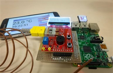
If you’re on a home budget then it is possible to make a simple thermocouple system with a Texas Instruments development board and a Raspberry Pi.
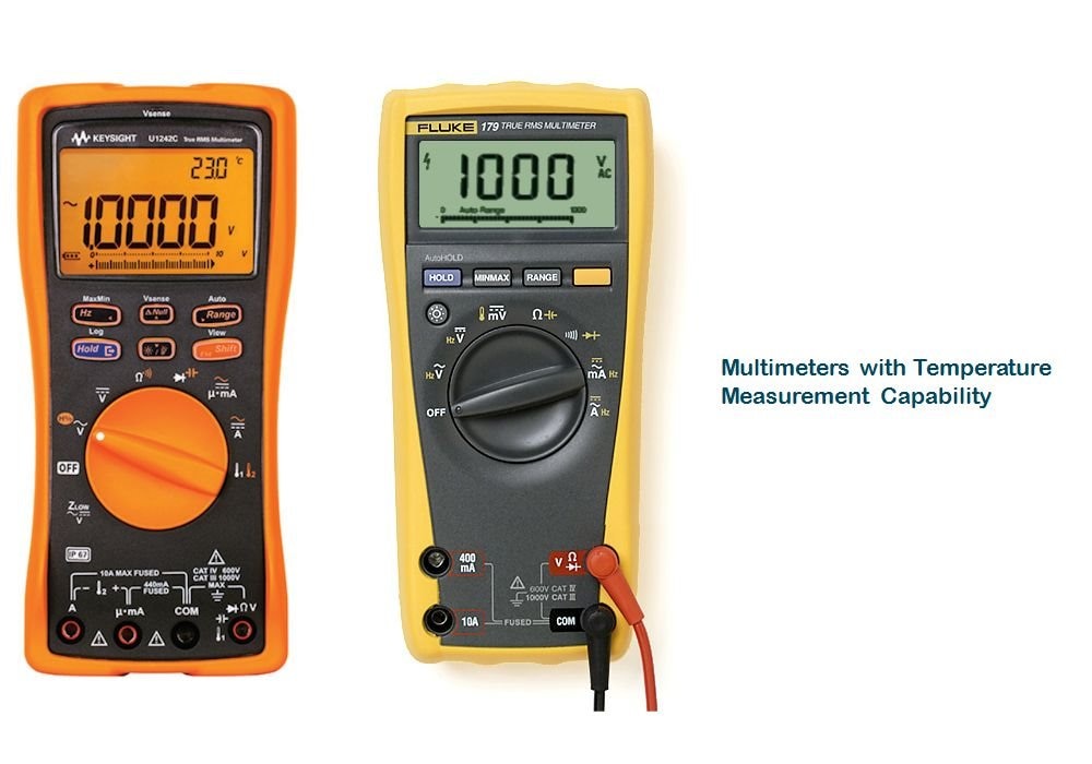
The thermocouple is extremely popular in labs especially because some multimeters support them! As a result it can be one of the lowest cost ways of measuring temperatures in a lab. A single thermocouple is never enough, so you may need to specify several multimeters and thermocouple kits for the lab.
| Model | Keysight U1241C U1241C or U1242CU1242C | Fluke 179Fluke 179 |
|---|---|---|
| Meter Range | -200 to +1372 degrees C | -40 to +400 degrees C |
| Meter Accuracy | 1% + 1 degree C | |
| Thermocouple Kit Part Number | U1186A U1186A or U1180AU1180A | 80BK-A80BK-A |
| Thermocouple Range | -20 to +200 degrees C | -40 to +260 degrees C |
Which method will be used?
This project relies on a thermistorthermistor; a device that has a resistance which varies with temperature. It has a number of advantages compared to many other sensors; it is tiny, has a fast response time and can be very accurate. It has its disadvantages too (some will be discussed later) but for a heat sink measurement scenario where a limited temperature range of about 100 degrees C is more than enough, the thermistor becomes very useful.
To measure the resistance we will be relying on a potential divider circuit. The thermistor forms one leg of a potential divider; the resultant output voltage is buffered and then converted into a digital value using an analog-to-digital converter (ADC). The digital data can be read by any processor board and logged, graphs plotted and so on.
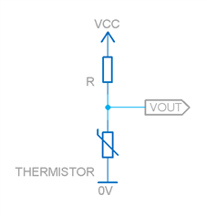
In theory the potential divider circuit is very simple; as the temperature rises, the resistance of the thermistor will decrease. This means that Vout will decrease too, and it can be measured.
Why a Thermistor?
They have a very rapid response time due to their size which provides a low thermal (heat) mass. It should be possible to measure a temperature accurately within seconds, compared to the TO92 plastic encased sensors which could take minutes to reach equilibrium.
Thermistor Characteristics
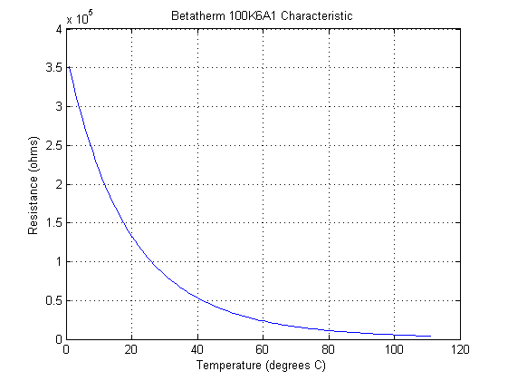
Thermistors change resistance as a temperature change occurs. The negative temperature coefficient (NTC) device selected for this project (Betatherm 100K6A1BBetatherm 100K6A1B) has a high resistance at cold temperatures, and a low resistance when it is hot. The resistance change is large however it is non-linear.
The graph for the specific device used for this project is shown here; at zero degrees Celsius the resistance is close to 350k ohms, and at 100 degrees C the resistance has dropped to close to 5k ohms.
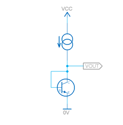
One school of thought is to use a current source and then measure the voltage across the thermistor. The approach works however it has a major disadvantage that it does not begin to address the non-linearity. It means a very high resolution ADC (24 bits or higher) is needed just to be able to handle the high temperature measurements with any decent resolution since the gradient on the curve is so shallow at those high temperatures. The required ADC resolution of 24 bits can be approximately guesstimated by examining the change in voltage that would occur for 1 degree C change (or 0.1 degree C change – depends on your desired output resolution) at the shallowest area on the curve which is at the upper temperature region, and seeing how many bits are needed to resolve such a difference in voltage.
Another approach is to construct a potential divider and size the fixed resistance appropriately such that the measured voltage is more linear. Then, after the signal has been digitised the exact reverse function can be applied by computation by the processor to get back to the original non-linear curve and then do a calculation to work out the temperature. The final result can be astonishingly accurate thanks to the work of Steinhart and Hart who in the 1960's came up with a mathematical model which very closely represents the actual resistance-temperature curve of thermistors. More on that in Part 2.
What value of resistor to use? This depends on the range of temperatures for which accuracy is needed.
As an example, the graph below (for 0 to 110 degrees C) shows the voltage across the thermistor when the resistor in the potential divider takes a value from 10k ohm to 120k in steps of 10k; the top curve is for 10k, and the bottom curve is for 120k.
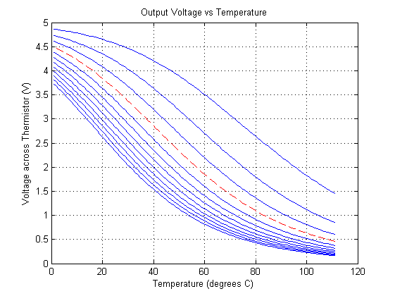
From this one might want to select the curve which is most straight; perhaps the red dashed curve which corresponds to a 30k resistance.
The benefit from doing this is huge; performing this linearization, the ADC requirements dramatically drop from perhaps 24 bits to 14 bits, if resolution sufficient for 0.1 degrees C is needed. Furthermore, even though the line is not exactly linear, it is well-defined. This means there is no major impact to accuracy because the opposite transformation will be applied by the software running on the processor. Were this an analog-only temperature measurement system, more care would be needed to perform better linearization. We don’t need to do that with this combined analog/digital solution.
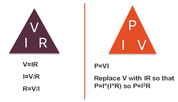
The actual resistor chosen was 33k ohm; this allows the inflection point of the curve to fall at almost exactly 50 degrees C which is a typically expected temperature for heat sink experiments. It is also important that the resistance is not too low and the voltage is not too high, because then a lot of current passes through the thermistor to cause self-heating. To calculate this, the power dissipated in the thermistor is calculated (using Ohm’s Law and the Power Equation) and compared with the ‘dissipation constant’ for the thermistor. If the power dissipated matches the dissipation constant then the temperature of the thermocouple will rise by 1 degrees C due to the current. As a result, a voltage of 2.048V was chosen and this combined with the 33k resistor selection meant that the error due to self-heating would be limited to under +-0.04 degrees C. These values should be ideal for thermistors down to about 1mm diameter; any smaller and the self-heating error would need to be further considered.
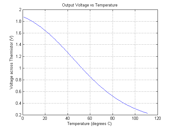
The graph below shows the output with 2.048V powering the potential divider circuit (33k ohm resistor and the thermistor). It shows that as long as the subsequent analog to digital converter (ADC) stage can handle an input between 1.9V down to 0.2V, a range of zero to 100 degrees C can be covered. Beyond these limits, the curve becomes shallower again and some accuracy and resolution will be lost.
Buffering the Signal
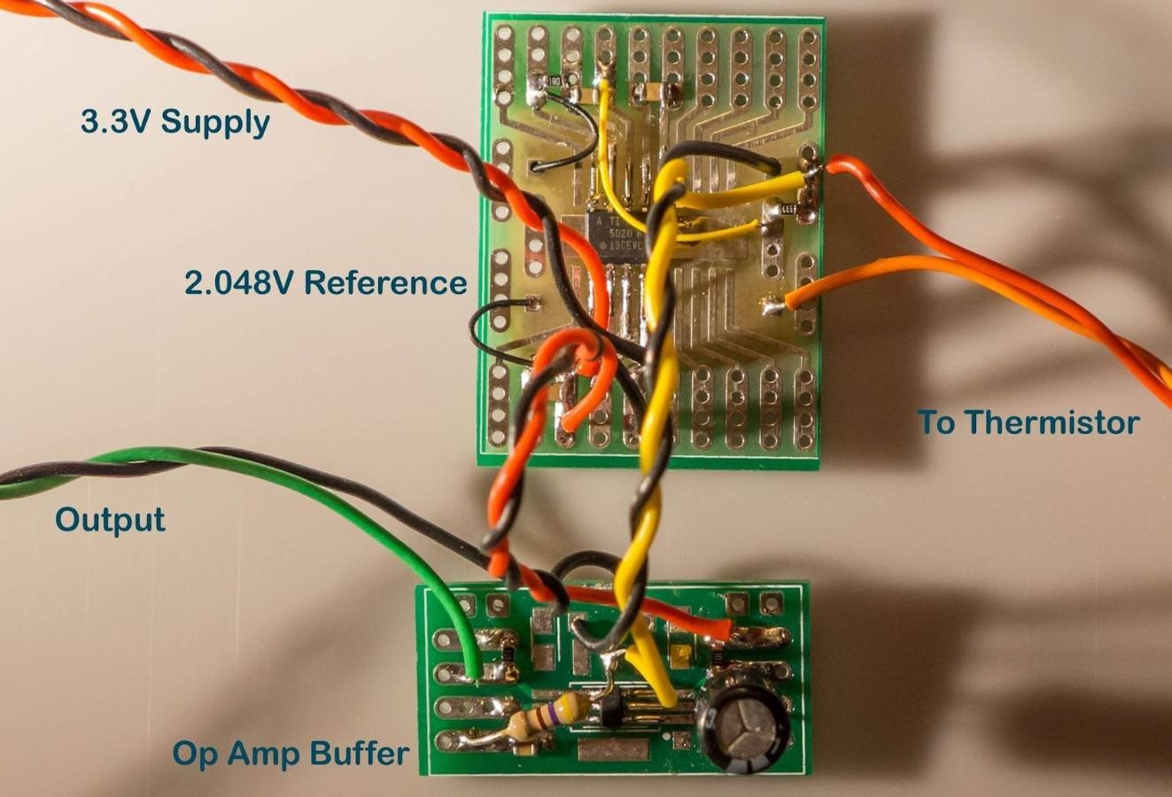
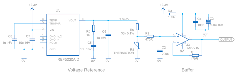
Because the resistance of the thermistor varies so greatly and takes on a very high resistance at low temperatures, the signal is inappropriate for feeding into an ADC without buffering. The choice of buffer was a fairly easy decision; Texas Instruments has some op amps with extremely low input bias current. The LMP7715 was chosen and a conventional non-inverting buffer circuit was used.
For increased accuracy a 2.048V source was created using the REF5020 integrated circuit. The entire circuit can be powered from a 3.3V supply.
Building and Testing the Circuit
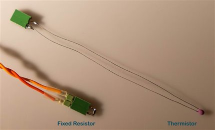
Eventually a PCB will be designed but the prototype was constructed on SMD adapter boards. To test it out, the thermistor was temporarily replaced with a fixed resistor to simulate any temperature of interest. I used a 20k ohm resistor and then observed the output on an oscilloscope. However, any noise on the signal was below the measuring capability of my scope and probe. The output voltage level was at the expected voltage (770mV) given the accuracy of the resistor was just 1%.
Next it was time to bring out the highest resolution voltmeter I could find. This was a very old Keithley 2000 series multimeter (out of calibration unfortunately, but for now I was more interested in the noise on the signal and any observable drift). The video below shows the signal was stable enough to not cause any measurement issue over the short term – any noise only had an effect down to the 6th digit after the decimal point (the software part of the design will also implement some filtering, by reading the temperature repeatedly and then averaging).
The circuit was powered off, and the experiment repeated the next day. This time the multimeter and the circuit were allowed to warm up for 30 minutes, and measurements made every ten minutes after this, for an hour. These measurements after the 30 minutes were flat and the measurement was now being limited by the multimeter; only the 6th digit after the decimal point changed during that hour. (For reference, the measured values were: 0.774260, 0.774261, 0.774263, 0.774265, 0.774267, 0.774266, 0.774262V ). Ambient temperature was not measured for this initial test although this needs to be done to see if there is any impact.
From the measured results (Around 110uV difference over the data points from the day before and the following day although there was a change of power supply too), the impact to the measured temperature result would be less than five 1-thousandths of a degree C. This is comforting; when it comes to the PCB implementation the supply circuit can be improved to further stabilise the results.
At this level of resolution all sorts of interesting effect can be observed. Just blowing on the circuit can cause some microvolts of change. The final enclosure and PCB design will need to achieve a few things. The enclosure will prevent drafts. If parts of the circuitry consume more current then they will get warmer than other parts. As a result the voltage reference and the op amp will need to be separated from one another to minimise heating each other up since each one uses a few mW of power. They will need to be kept separated from the 33k resistor in the potential divider circuit which consumes two orders of magnitude less power. The PCB can have slots to increase the thermal resistance between the resistor and the remainder circuitry.
Next Steps
More tests need to be done, but the initial results are promising enough to continue with the design. The next part of the design will examine the digital portion of the project. The analog part of the design will be slightly refined too. And most importantly finally the question can be answered to some degree of accuracy, is the perfect room temperature really 23 degrees C?
Top Comments