


Note: This is part 2 of a two-part project.
For first part, see here: Building a Low Cost Solder Fume Extractor – Part 1
Introduction
This project concerns a solder fume extractor that does as the title suggests, and sucks up solder fumes from soldering irons : ) It consists of a box containing multiple fans and filters, and a hose attachment with a funnel on the ingress side, and an egress side with the control/connectors. There is also an 'Aux' port, for additions such as LED lamps, static dissipation, and touch/touch-less control.
Building a Low Cost Solder Fume Extractor – Part 1 covered most of this project more than a year ago, and unfortunately this Part 2 was intended to be released shortly afterwards, but I didn’t get a chance to complete it. However, I still had the photos for Part 2, and so I’ve decided that this Part 2 blog post will cover the essentials to complete the project. It is mainly some assembly tips, since all the parts and cutting dimensions and wood assembly steps were covered in Part 1. Also, please see the comments section in Part 1 for more discussion.
Any wood or other component names beginning with capitals (such as Ingress Plate) are defined in a table or the diagram in part 1.
Part 1 left off with the wood construction mainly complete.
Assembling the Ingress side
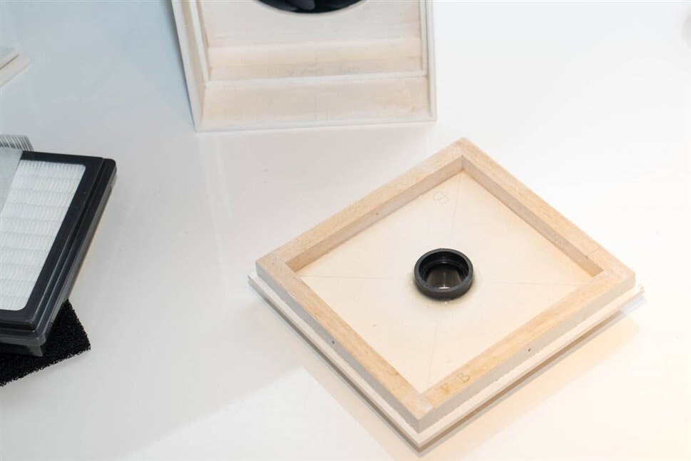
The photo here shows the Ingress Plate and 12x12mm dowel frame (Ingress Frame) glued together, so that it can plug onto the main body of the unit. Normal wood glue (PVA) is used. The hose connector (see part 1 for the URL to purchase it) is epoxied in place. I drilled 3mm holes in a large circle, and then sanded to make the hole for it.
I spray-painted everything on the outside, and then set about assembling the ingress side.
The photo below shows the three filters all ready for inserting into the main unit. Sticky tape folded back on itself was used to create two flaps for easy removal of the HEPA filter at a later date.
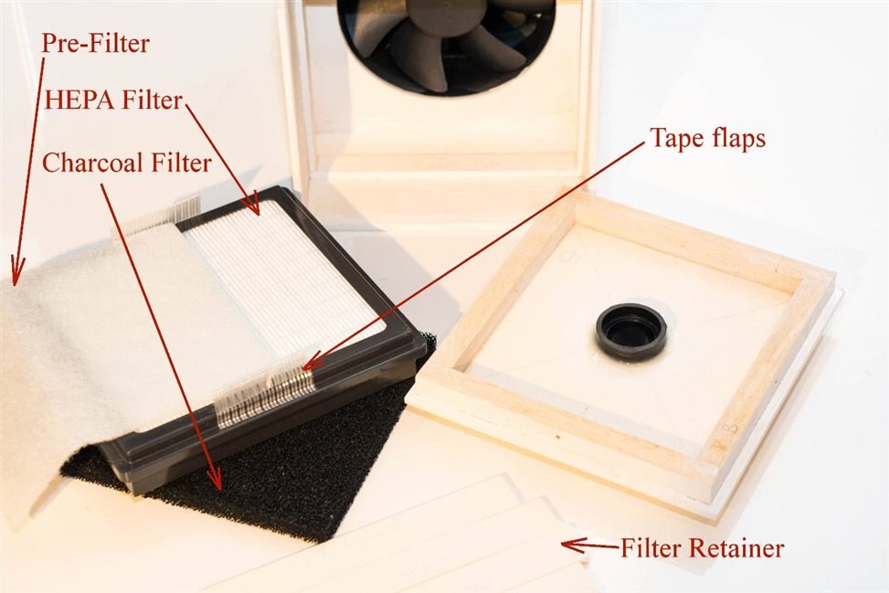
The filters were inserted into the unit, with the charcoal filter first, followed by the HEPA filter. Next the four Filter Retainer wood slats were placed inside so that they were against the sides of the HEPA filter. They are not glued, they are intended to be removable.
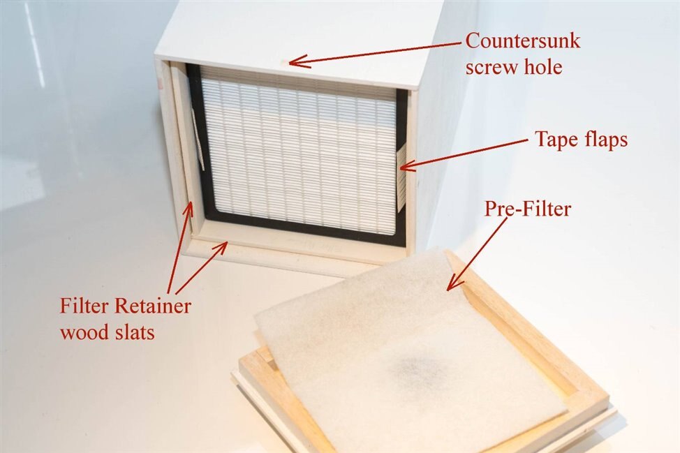
The Pre-Filter was placed inside, and then the Ingress Plate/Ingress Frame was plugged into place (the Ingress Frame presses against the edges of the Filter Retainer wood slats, holding the HEPA filter in place. Small wood screws are used to secure the Ingress Frame, until the filters need replacing. The photo below shows it assembled, with the hose plugged on.
Assembling the Egress side
The egress end of the main unit houses the connectors. There isn’t a lot of space : ( With hindsight, the design would be slightly larger, since everything was a tight squeeze, making it more awkward to disassemble at a later date for any fan servicing. Its is still possible, just difficult due to the size. I had not initially anticipated needing some circuitry for current limiting during start-up (since of course the fans are a very heavy load until they’re spinning), and adding that took up the space : (
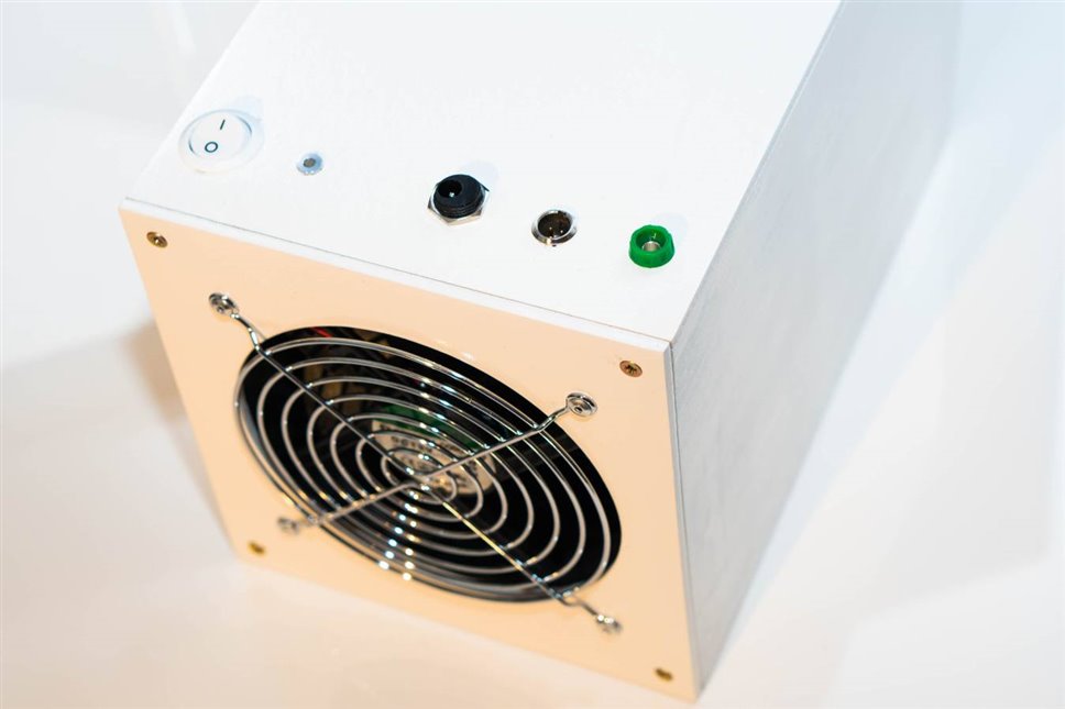
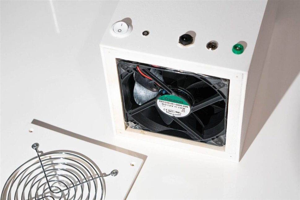
The photo below shows the connectors, LED and switch all fitted (for hole dimensions, see part 1). The Aux connector is wired to the switched DC, so that in future an LED lamp can also be powered from the same supply. The green 4mm banana socket is internally connected via a 1 Mohm resistor to a pin on the Aux connector. This is so that optional grounding is possible of the anti-static hose or any future accessory.
The Egress Plate has a large hole for the grille, (it was drilled using the technique described in part 1 – basically draw a large circle with a compass, then make lots of small holes, cut it out and sand it). Pop-rivets can be used to secure the grille, or short screws (long screws will hit the fan blades).
Note that the circuit is not shown (I unfortunately did not draw it up at the time) but it basically consisted of a MOSFET that shorted a power resistor after a few seconds (using an RC circuit) so that inrush current is limited by the power resistor initially. It isn’t a pretty circuit, I’m sure better circuits are possible.
Putting it Together
Once the main unit is assembled and the ingress side is fitted, all that remains is to push in the fan pack, and screw on the egress plate. However, with hindsight, I would have modified the assembly steps slightly. This is because it is very important for the fans to be air-tight against the Fan Ingress Surround (for reference, the diagram of part names is repeated here from part 1):
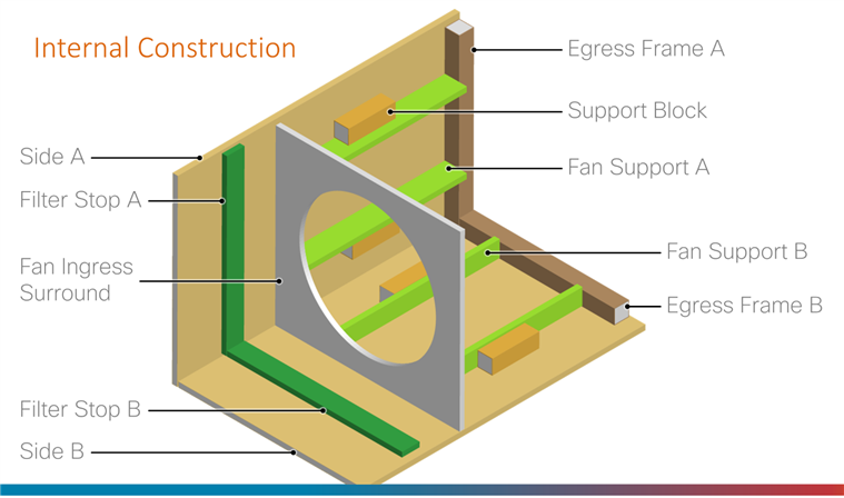
It is difficult to achieve air-tightness by just pushing in the fan pack, without some soft foam gasket of some sort. That may entail increasing the dimensions of the main unit slightly. Another approach is not to glue all four sides of the main unit, and leave one side open until the fans are inserted, and glue the fan to the Fan Ingress Surround. That makes it awkward to replace the fan at a later date however.
The reason for the air-tightness, is that since the HEPA filter is very dense, air tends to short-circuit in a loop around the fan pack, unless there is air-tightness to force the air from the filter side of the fan surround to enter the fan side.
The filter side doesn’t seem to need gluing, since the Filter Retainer and the Filter Stop slats make it quite difficult for air to bypass the HEPA filter, but still some thin foam there could help too perhaps.
Fume extraction funnel
Although the hose end could be used as-is, if you have a 3D printer then a more fancy end could be created.
I’m a 3D beginner, so my design is very crude. It fits the hose mentioned in part 1:
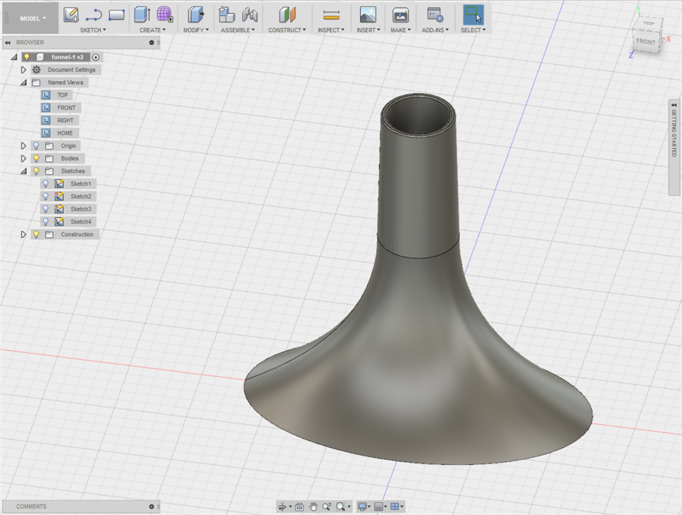
The Autodesk Fusion 360 model can be downloaded here (Autodesk 360 cloud sharing feature): https://a360.co/2OzseAB
Summary and Fume Extraction 2.0
With a bit of woodwork, a usable solder fume extractor can be created using common PC fans, although the order code in part 1 is I think a good suggestion. It is recommended to increase dimensions by around 1 cm, to have more space for electronics, and to have space for foam gaskets where required.
The unit functions, but care is needed to obtain air-tightness between each fan, and to the Fan Ingress Surround and to the HEPA filter, all due to the density of the filter. With such care, I believe it functions far better than the low-cost desktop fume extractors. There are many places where the design could be improved, and there is a huge opportunity to make it far better than old-school fume extractors which are featureless.
As an example, although this project is compact, as an ultra-compact design for home labs, it could be worth exploring using server fans. Since servers are often 1 rack unit, or 2 rack units in height, the fans are smaller, and usually super-powerful. Several of those stacked together might work very well. A smaller HEPA filter would be needed for the smaller fans. I’ve not tried cutting one, but perhaps that is an option.
One other feature I wanted to implement, was a touch-on/touch-off capability, so that the system can be switched on/off without diverting the eyes off the hot soldering iron, just by reaching out and tapping the hose or even just a hand-wave. This is feasible because the hose is conductive. A capacitance input such as available with some microcontrollers, alternatively the excellent FDC2214 – Texas Instruments FDC2214 Capacitance to Digital - Review could be a possibility; there's a project there under the section Building a Touchless Switch to have wave-on/wave-off capability with the FDC2214.
In summary I think there are lots of exciting possibilities for future designs, so that many home labs are equipped with functional and feature-rich fume extraction systems. I hope the information in this two-part project was useful. If you have any ideas or other implementations, it would be great to hear about them!


