element14 Community
element14 Community
    Register Log In
  • Site
  • Search
  • Log In Register
  • Members
    Members
    • Benefits of Membership
    • Achievement Levels
    • Members Area
    • Personal Blogs
    • Feedback and Support
    • What's New on element14
  • Learn
    Learn
    • Learning Center
    • eBooks
    • STEM Academy
    • Webinars, Training and Events
    • Learning Groups
  • Technologies
    Technologies
    • 3D Printing
    • Experts & Guidance
    • FPGA
    • Industrial Automation
    • Internet of Things
    • Power & Energy
    • Sensors
    • Technology Groups
  • Challenges & Projects
    Challenges & Projects
    • Design Challenges
    • element14 presents
    • Project14
    • Arduino Projects
    • Raspberry Pi Projects
    • Project Groups
  • Products
    Products
    • Arduino
    • Dev Tools
    • Manufacturers
    • Raspberry Pi
    • RoadTests & Reviews
    • Avnet Boards Community
    • Product Groups
  • Store
    Store
    • Visit Your Store
    • 'Choose another store...'
      • Europe
      •  Austria (German)
      •  Belgium (Dutch, French)
      •  Bulgaria (Bulgarian)
      •  Czech Republic (Czech)
      •  Denmark (Danish)
      •  Estonia (Estonian)
      •  Finland (Finnish)
      •  France (French)
      •  Germany (German)
      •  Hungary (Hungarian)
      •  Ireland
      •  Israel
      •  Italy (Italian)
      •  Latvia (Latvian)
      •  
      •  Lithuania (Lithuanian)
      •  Netherlands (Dutch)
      •  Norway (Norwegian)
      •  Poland (Polish)
      •  Portugal (Portuguese)
      •  Romania (Romanian)
      •  Russia (Russian)
      •  Slovakia (Slovak)
      •  Slovenia (Slovenian)
      •  Spain (Spanish)
      •  Sweden (Swedish)
      •  Switzerland(German, French)
      •  Turkey (Turkish)
      •  United Kingdom
      • Asia Pacific
      •  Australia
      •  China
      •  Hong Kong
      •  India
      •  Korea (Korean)
      •  Malaysia
      •  New Zealand
      •  Philippines
      •  Singapore
      •  Taiwan
      •  Thailand (Thai)
      • Americas
      •  Brazil (Portuguese)
      •  Canada
      •  Mexico (Spanish)
      •  United States
      Can't find the country/region you're looking for? Visit our export site or find a local distributor.
  • Translate
  • Profile
Open Source Hardware
  • Technologies
  • More
Open Source Hardware
Blog Building a Mini 5V Supply in a DB-25 Shell
  • Blog
  • Forum
  • Documents
  • Events
  • Polls
  • Members
  • Mentions
  • Sub-Groups
  • Tags
  • More
  • Cancel
  • New
Open Source Hardware requires membership for participation - click to join
Blog Post Actions
  • Subscribe by email
  • More
  • Cancel
  • Share
  • Subscribe by email
  • More
  • Cancel
Group Actions
  • Group RSS
  • More
  • Cancel
Engagement
  • Author Author: shabaz
  • Date Created: 27 Nov 2021 1:42 PM Date Created
  • Views 43608 views
  • Likes 11 likes
  • Comments 9 comments
  • data-logging
  • sensors
  • power supply
  • das240-bat
  • LT3089
  • data logging
  • data_logging
Related
Recommended

Building a Mini 5V Supply in a DB-25 Shell

shabaz
shabaz
27 Nov 2021
Building a Mini 5V Supply in a DB-25 Shell

Table of Contents

  • Introduction
  • Circuit
  • Construction
  • Output Noise
  • Summary

Introduction

This is quite a niche blog post, but may be relevant for anyone who needs a simple, quick, low-noise power supply! This project is PCB-less, it can be very quickly scratched out onto 'resin bonded paper' FR2 copper-clad board, and made to fit into a small enclosure.


My use-case was to connect the power supply to operate sensors, for monitoring with a useful product called DAS240-BAT (click here for a review of it). The DAS240-BAT is a great data recorder. It has lots of channels, electronic switching, and a large display for real-time charting of measurements. (There's also a more integrated DAS220-BAT which I think would suit more users and is lower-cost, and the information below is relevant to both models, although I'll just refer to the DAS240-BAT since that is what I used/tested).


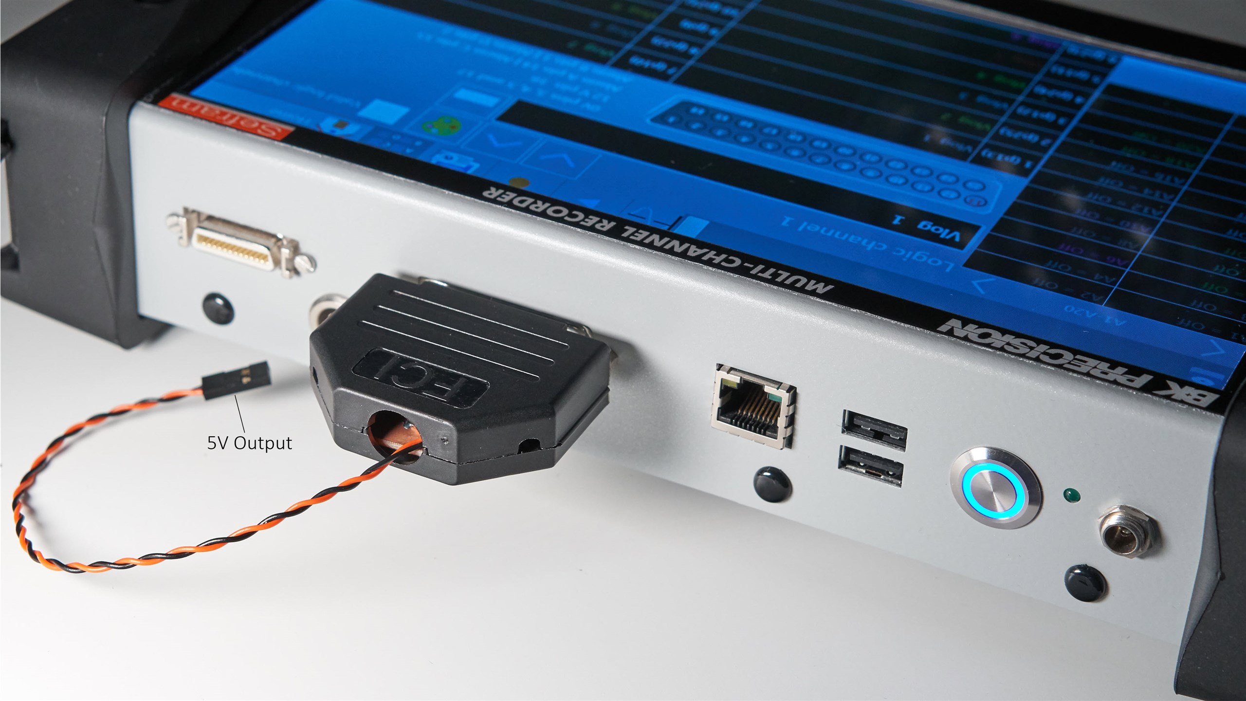
All types of sensors with a voltage output can be directly attached to the DAS240-BAT. Some sensors may require an external power supply or amplifier to operate. There is an almost undocumented feature on the DAS240-BAT that simplifies this – there is a DC power supply output on pins on a 25-way D-Sub connector (DB-25) on the instrument. This project is really simple – it's a small voltage regulator that attaches to that DB-25 connection, to provide 5V for external sensors.

image

Circuit

The DAS240-BAT supplies approximately 12V at up to 200 mA, which is more than enough to power up a few sensors hopefully. One approach would be to just wire up a 7805 regulator and call it a day. I wanted to have a supply with lower noise, in case it affected attached sensors. Hunting through the semiconductor parts bin, I found an LT3089 which seemed perfect – it has low noise (27uV RMS), and can support output current to beyond what the DAS240-BAT can supply anyway, plus the package is really nice for prototyping (it's almost like a surface-mount alternative to TO-220, but with seven pins), and allows for simple heatsinking to a circuit board.

image

Construction

I used single-sided copper-clad FR2 board (it blunts tools less than FR4, and is quite cheap from Aliexpress) and first cut it to size, held the LT3089 chip to it and used a pencil to mark off the location of each of the pins, and then used a 'Scorper' tool to quickly score out the relevant pads for this project. See here for more information on the scorper tool.  A knife could be used too. It's very quick, there's not a lot to do for this project! The layout I used is shown below (click to enlarge):

image
Ten minutes later, the work was complete with the few components soldered. Although I didn't use it here, for a complete ground plane, it is possible to apply adhesive copper tape on the underside of the board (I have not found a source of double-sided copper-clad FR2 board).

image

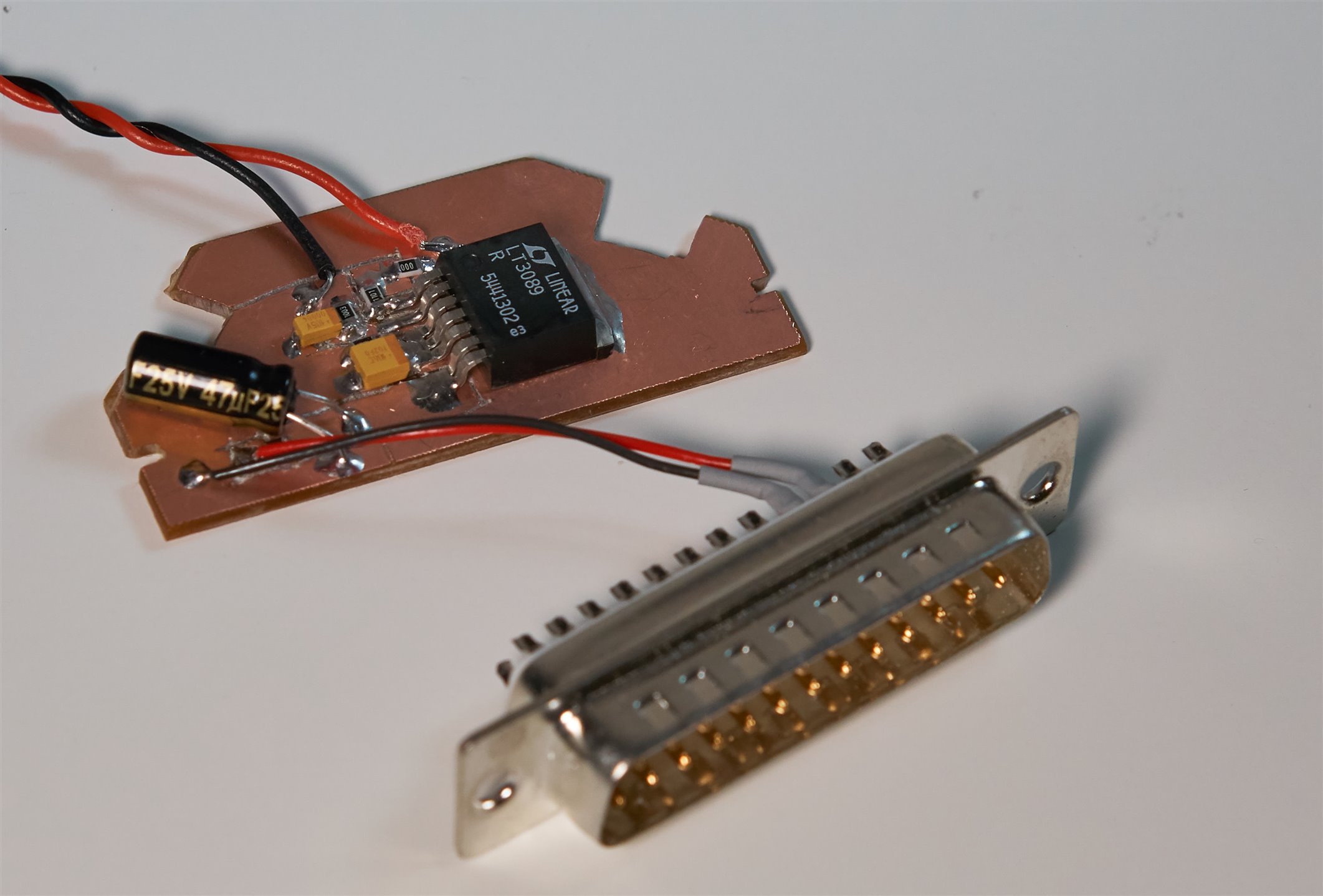
Here is what it looks like sitting inside the DB25 plastic backshell:

image


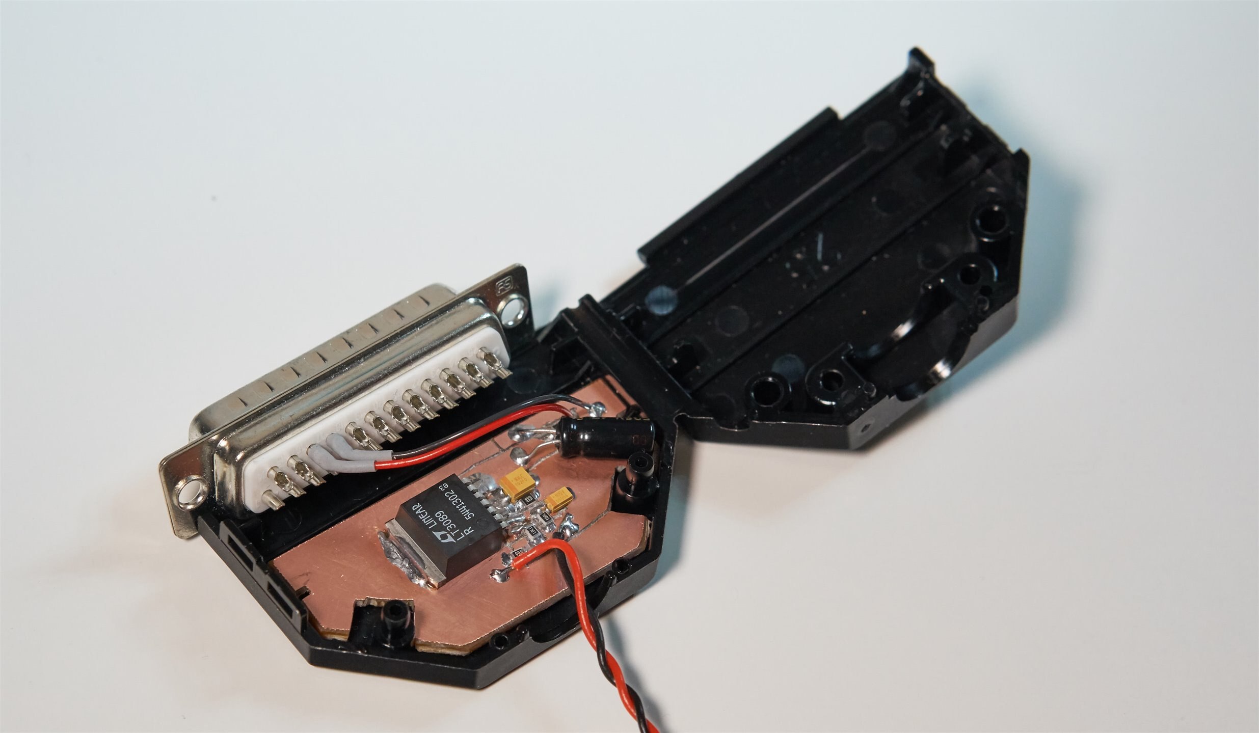
After some basic testing, I superglued the wires in place and snapped the backshell shut. Project complete : )


Output Noise

I attached a 100 ohm resistor on the output, so that the load was 50mA (this seemed reasonable for a few sensors), and then tested the supply under three scenarios; (a) inside a biscuit tin powered from a 12V bench supply, (b) in free air powered from a 12V bench supply, and (c) in free air powered from the DAS240-BAT while it was running data acquisition on two channels. The output was connected to a measurement amplifier set to 10 kHz bandwidth, and gain of 100. For more information on the measurement amplifier, click here.

image

For all three scenarios, the result was almost identical; I could not notice a difference. The 'scope trace shows from the automated measurement at the bottom that RMS noise was 1.21mV divided by 100, i.e. 12uV RMS, which is not bad:

image


With just over 500 kHz bandwidth (all filters disabled on the measurement amplifier), the output noise is as shown below, about 25uV RMS.

image

Summary

This was a basic one-evening project, and it turns out that the LT3089 makes a great low-noise supply. I was happy that no circuit board needed to be designed and ordered for this project; it was quicker to just score out the pads on the FR2 board. 


Thanks for reading!

  • Sign in to reply

Top Comments

  • genebren
    genebren over 1 year ago +2
    Great project/blog. What a handy way to power sensors. I have a bunch of power supplies (fixed and adjustable), but there never seems to be enough for some projects. Well done!
  • Workshopshed
    Workshopshed over 1 year ago

    Second time I've seen this assembly technique recently, the other project called it "Manhatten style" 

    • Cancel
    • Vote Up 0 Vote Down
    • Sign in to reply
    • More
    • Cancel
  • shabaz
    shabaz over 1 year ago in reply to javagoza

    Hi Enrique,

    Thanks!

    • Cancel
    • Vote Up 0 Vote Down
    • Sign in to reply
    • More
    • Cancel
  • shabaz
    shabaz over 1 year ago in reply to jc2048

    Hi Jon,

    Thanks for spotting that! I'll get the component symbol corrected.

    • Cancel
    • Vote Up 0 Vote Down
    • Sign in to reply
    • More
    • Cancel
  • javagoza
    javagoza over 1 year ago

    A very smart and practical design. Congratulations.

    • Cancel
    • Vote Up 0 Vote Down
    • Sign in to reply
    • More
    • Cancel
  • jc2048
    jc2048 over 1 year ago

    That board looks nice and neat. Excellent presentation, as well.

    I think your drawing of the internals of the device on your circuit diagram must be slightly wrong. The internal current source would drive R1 to give a reference voltage, wouldn't it, and that would then be compared with the output voltage to control the regulator; it wouldn't work with the output and the reference connected together like you've shown. 

    image

    Not that it affects anyone building it, of course. The external circuit is no different.

    • Cancel
    • Vote Up 0 Vote Down
    • Sign in to reply
    • More
    • Cancel
>
element14 Community

element14 is the first online community specifically for engineers. Connect with your peers and get expert answers to your questions.

  • Members
  • Learn
  • Technologies
  • Challenges & Projects
  • Products
  • Store
  • About Us
  • Feedback & Support
  • FAQs
  • Terms of Use
  • Privacy Policy
  • Legal and Copyright Notices
  • Sitemap
  • Cookies

An Avnet Company © 2023 Premier Farnell Limited. All Rights Reserved.

Premier Farnell Ltd, registered in England and Wales (no 00876412), registered office: Farnell House, Forge Lane, Leeds LS12 2NE.

ICP 备案号 10220084.

Follow element14

  • X
  • Facebook
  • linkedin
  • YouTube