


Introduction
The aim of this project was to design a simple radio receiver that anyone could assemble by deliberately using large surface-mount components.

The final design is very low-cost (approx. £20 GBP or $25 USD not including the speaker, but the cost reduces to perhaps half of that if assembling several of them, due to minimum order quantities of some parts), and normal soldering tools can be used to assemble the circuit. It can be fully constructed within a few hours. There is no circuit adjustment or trimming needed, and the prototype worked the first time – it's very easy to have a successful result the first time with this project.
There is a 3-minute video explanation and demo of it here:
I'm convinced that children could assemble this circuit. After watching sub-10-year-olds soldering a couple of surface-mount integrated circuits (see photos below), I was encouraged that surface-mount technology was not difficult for them! If anything, occasionally through-hole components posed more of a problem.
Of course, to solder surface-mount successfully they had to use a reasonably small soldering tip size (around 1 mm) and thin solder (0.38 mm diameter is great) and some of the components had to be taped into position, or Blu-Tack (repositionable putty) can come in handy.
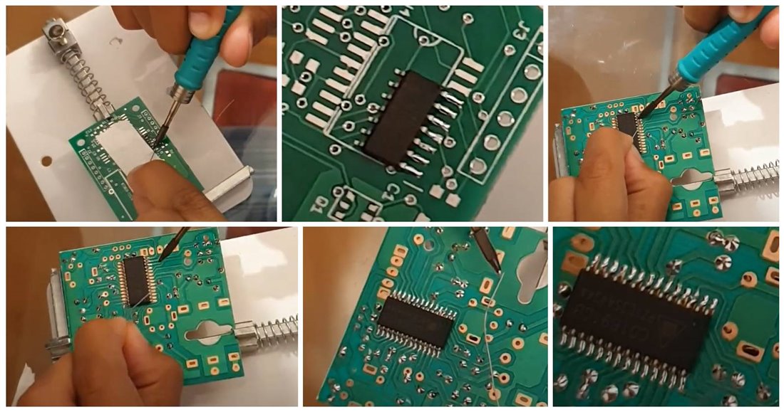
Working in pairs, it should be possible for one child to hold a surface-mount component in position with tweezers, while the other solders it.

Radio Circuit
The radio circuit is based around a single integrated circuit (IC), Silicon Labs SI4825, and not much else. The SI4825 accepts a variable resistor (potentiometer) to act as the tuning control.
The circuit is shown below. The FM antenna input is pin 1 on connector J3 on the far left side of the circuit. Pins 2 and 3 on that connector are for AM mode, which isn't implemented.

The right-side portion of the circuit consists of a string of resistors that are used to select the desired frequency band and mode. There is a chain of resistors to select the frequency band, the idea being that a multi-way switch can be used to select a tap point between resistors. In my case, I decided to not connect any switch there and I soldered a wire jumper to permanently select the FM broadcast band.
By changing the resistor values, or by moving the wire jumper or wiring a switch there, the SI4825 can be reconfigured to support AM broadcast and short-wave modes, or different region FM bands. The circuit diagram and the circuit board are labeled with the wire jumper position to select the FM band for Europe or the USA region (for other regions, the SI4825 datasheet will need to be examined).
Tuning is achieved by adjusting the potentiometer VR1, and the audio appears on pin 16 of the IC. An antenna wire is soldered to pin 1 of connector J3. The circuit is powered from 3V, so two AA or AAA batteries can be used. The circuit diagram shown here forms the entire radio apart from the audio amplifier! It's impressive how few components are needed.
Amplifier Circuit
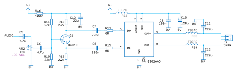
The circuit below forms the audio amplifier that connects to the audio output pin from the radio chip. The audio can be adjusted for volume using the potentiometer VR2 shown on the left side of the circuit below. The audio is amplified/converted to differential signals using the transistor Q1. The integrated circuit U2 is an audio amplifier chip to drive the 8-ohm speaker.
Power Entry
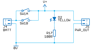
A 3V battery (two AA cells) connected to J4 is used to light an LED and provide power to the rest of the circuit.
Circuit Board
The PCB files are attached to this blog post. Large 0805-sized surface-mount components are used for ease of assembly. In terms of layout, the top half of the circuit board contains the radio circuitry. The lower half contains the audio amplifier. The right side of the board is a detachable portion containing just the power entry part of the circuit. The idea was that depending on the particular enclosure, it may be desirable to place the switch and LED in a different location, and in that case, the power entry part of the board can be separated and extended with a couple of wires.
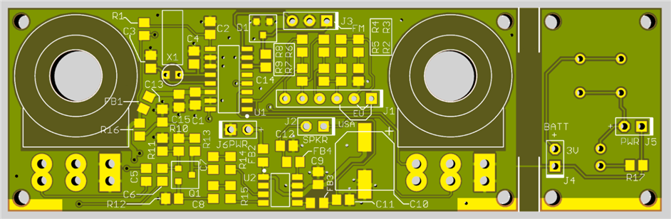
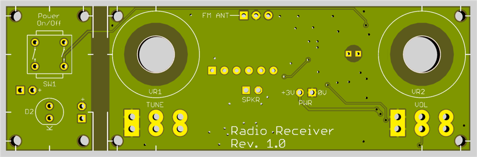
The completed board is shown in the photo below. It's quite quick to solder. The yellow wire acts as the FM antenna. The twisted black wires go to a 2-inch diameter 8-ohm speaker. The power wires on the right side attach to the 2xAA battery holder.

Wiring Diagram
The diagram below shows the required connections. The region selection wire is shown in the Europe position (shorting pins 1 and 2) but for the USA region, pins 1 and 3 need to be shorted instead.
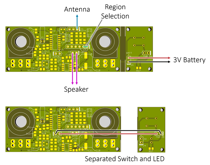
If the power switch and power LED are separated from the remainder, then two wires are used to electrically connect them as shown above.
Soldering
The general procedure I use is to solder in all the smaller components first, particularly the resistors, and then the capacitors. Once all the smaller parts have been soldered in, then the transistor, the crystal, and the two ICs can be soldered in. All the through-hole parts are soldered last.
Enclosure
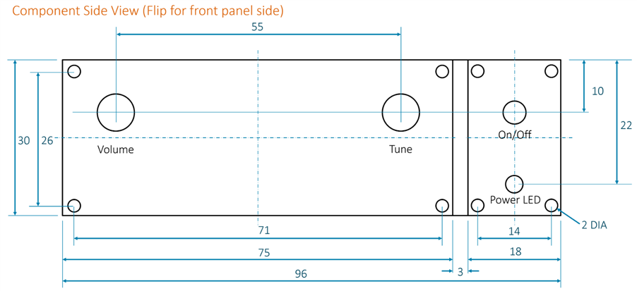
The dimensions of the circuit board are shown below. This is from the component side of the board, so it needs to be flipped around if it will be used to mark out a panel from the front side. The hole diameters required on the front panel for the power switch and the potentiometers depend on the specific parts used.
I plan to use a sweets tin and secured the circuit board inside using epoxy resin glue (alternatively a 3D printer could be used to create brackets or an entire enclosure).
See Building a Simple Radio - Part 2 - Final Assembly

Components and Parts List
Most of the parts are available from Farnell. Resistors R2 to R9 need to be 1% tolerance, these are low-cost 'thick film' parts. See the parts list below.
Potentiometers
I used potentiometers from Aliexpress, but I later found that Farnell has the correct sized ones too, at a low cost. The Aliexpress search term is WH148 and there are lots of online stores selling them. These potentiometers are available in different heights, and the circuit board is compatible with 12.5 and 15 mm versions (20 mm may be hackable into place). The volume potentiometer should preferably be a log type, but the tuning potentiometer must be linear type. The precise values are not important, but 10k is a good ballpark for the volume potentiometer, and 100k to 500k will work for the tuning potentiometer (I used 100k).
The knobs for the potentiometers were also from Aliexpress.
Speaker
I used an 8-ohm speaker from Aliexpress, 2-inch diameter.
Parts List
The list below does not include the speaker (8 ohms), and knobs (6mm serrated), and enclosure. All resistors are 1% thick film.
The parts are listed in the preferred order of soldering (i.e. smallest parts first).
| # | Mnfr Code | Description | Identifier | Qty |
|---|---|---|---|---|
| 1 | MCWR08X1003FTLMCWR08X1003FTL | 100k 0805 | R1 | 1 |
| 2 | MCWR08X4702FTLMCWR08X4702FTL | 47k 0805 | R2 | 1 |
| 3 | MCWF08P1002FTLMCWF08P1002FTL | 10k 0805 | R3, R4, R5, R6 | 4 |
| 4 | RK73H2ATTD3903F.RK73H2ATTD3903F. | 390k 0805 | R7 | 1 |
| 5 | MCWR08X2202FTLMCWR08X2202FTL | 22k 0805 | R8, R10 | 2 |
| 6 | MCWR08X1001FTLMCWR08X1001FTL | 1k 0805 | R9 | 1 |
| 7 | MCWR08X2702FTLMCWR08X2702FTL | 27k 0805 | R11 | 1 |
| 8 | MCWR08X2201FTLMCWR08X2201FTL | 2.2k 0805 | R12, R13 | 2 |
| 9 | ERJ6GEY0R00VERJ6GEY0R00V | 0R 0805 | R14, R15 | 2 |
| 10 | ERJ6ENF1000VERJ6ENF1000V | 100R 0805 | R16, R17 | 2 |
| 11 | MMZ2012S601AT000MMZ2012S601AT000 | FBEAD 0805 | FB1, FB2, FB3, FB4 | 4 |
| 12 | MC0805B104K101CTMC0805B104K101CT | 100nF 0805 | C1, C2, C9 | 3 |
| 13 | C0805C220J5GACTUC0805C220J5GACTU | 22pF 0805 | C3, C4 | 2 |
| 14 | C2012X7R1E475K125ABC2012X7R1E475K125AB | 4.7uF 0805 | C5, C6, C15 | 3 |
| 15 | CC0805KRX7R7BB224CC0805KRX7R7BB224 | 220nF 0805 | C7, C8 | 2 |
| 16 | C0805C221K5GACTUC0805C221K5GACTU | 220pF 0805 | C11, C12 | 2 |
| 17 | GRM21BR61A226ME51LGRM21BR61A226ME51L | 22uF 0805 | C13 | 1 |
| 18 | X32K768L104X32K768L104 | 32.768kHz | X1 | 1 |
| 19 | BAV99BAV99 | BAV99 | D1 | 1 |
| 20 | BC849BLT1GBC849BLT1G | BC849B | Q1 | 1 |
| 21 | SI4825-A10-CSRSI4825-A10-CSR | SI4825 | U1 | 1 |
| 22 | PAM8302AADCRPAM8302AADCR | PAM8302 | U2 | 1 |
| 23 | 16SVPC100M16SVPC100M | 100uF 16V | C10 | 1 |
| 24 | P160KNP-0QC20B100KP160KNP-0QC20B100K | 100k Lin Pot | VR1 | 1 |
| 25 | P160KNP-0QC20A10KP160KNP-0QC20A10K | 10k Log Pot | VR2 | 1 |
| 26 | PVA1 EE H1 3.5N V2PVA1 EE H1 3.5N V2 | Switch | SW1 | 1 |
| 27 | L-53LYDL-53LYD | LED Yellow | D2 | 1 |
| 28 | MP000329MP000329 | 2xAA Batt Holder | J4 | 1 |
Summary
With little work, it is possible to make a usable radio with the Silicon Labs SI4825 chip. As mentioned, due to the simplicity it worked first time. The sound quality is similar to any typical portable radio. I think this could be a reasonable project for young children to work on, with a little supervision.
Thanks for reading!


