


Table of Contents
Introduction
Myself, and some friends from an amateur radio group (TDARS) decided to build an antenna analyzer! It’s not my design, although I created the printed circuit boards for this recreation of it. The original design is by amateur radio callsign VK5JST (Amateur Radio, May 2005), please refer to that for a deep dive into it.

The purpose of the antenna analyzer is to be able to tell you how well the antenna setup is matched to 50 ohms (it will provide a scalar value on a meter dial to help with this) at your desired transmit frequency.
This particular antenna analyzer relies on the user providing an RF source (usually a radio transmitter or transceiver), and then observing the deflection on a moving-coil meter, as the transmit frequency is varied around your desired frequency of interest, to see if the antenna is tuned to your desired frequency or not.
Note that the measurement is not as rich as you would obtain with a vector network analyzer VNA instrument), however, this antenna analyzer has the significant benefit that very little setup is needed and it’s quick to use, whereas the VNA requires a non-trivial amount of careful calibration before use, and therefore typically isn’t used as frequently as one might need to take some sort of measurement. A VNA is not a field instrument, and it’s far easier to accidentally make a mistake with that!
In a lab when you’re designing things, you’d use a VNA. It’s an instrument for design engineers, not normally for field use, although very-low-cost compact VNAs are now changing things slightly, so that, for a static setup where you have the time, you might consider using a VNA. However for a more frequent check, especially after say stormy weather, or after changing frequency, and possibly for mobile use, you’d very likely use an antenna analyzer. There is also far less chance for user error with an antenna analyzer, which is important when working with expensive high-power transceivers! Both instruments have their place.
If you want to build this antenna analyzer, you’ll find the circuit diagram, PCB files and loads of diagrams and photos to help assemble it, all at the antenna analyzer GitHub repository.
In brief, this is what needs to be done from a construction perspective (not including calibration):
(1) Order parts and printed circuit boards
(2) Build an enclosure
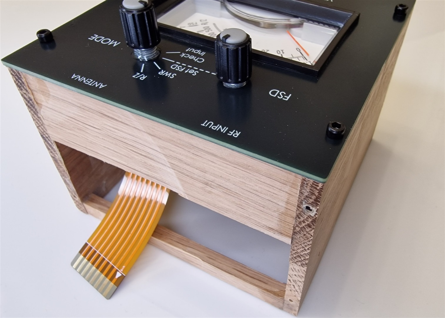
(3) Build the top panel (which contains a flexible PCB that houses the main rotary controls, and panel meter) and screw it onto the enclosure
(4) Solder the RF connectors onto the end panel and put it to one side
(5) Build the main board, which houses surface-mount parts and a couple of trimmer resistors
(6) Solder the end panel to the main board, at right-angles to each other
(7) Plug the combined end panel and main board onto the flexible PCB, and then screw it into the enclosure
Note: Although I used a wooden enclosure, this project is very easy to fit into any large plastic or metal enclosure, by cutting out holes for the top and side panels, or you could 3D print an enclosure (the precise dimensions of everything are at the antenna analyzer GitHub page).

Here are photos of two really nice 3D-designed enclosures, by callsign M0PLA.
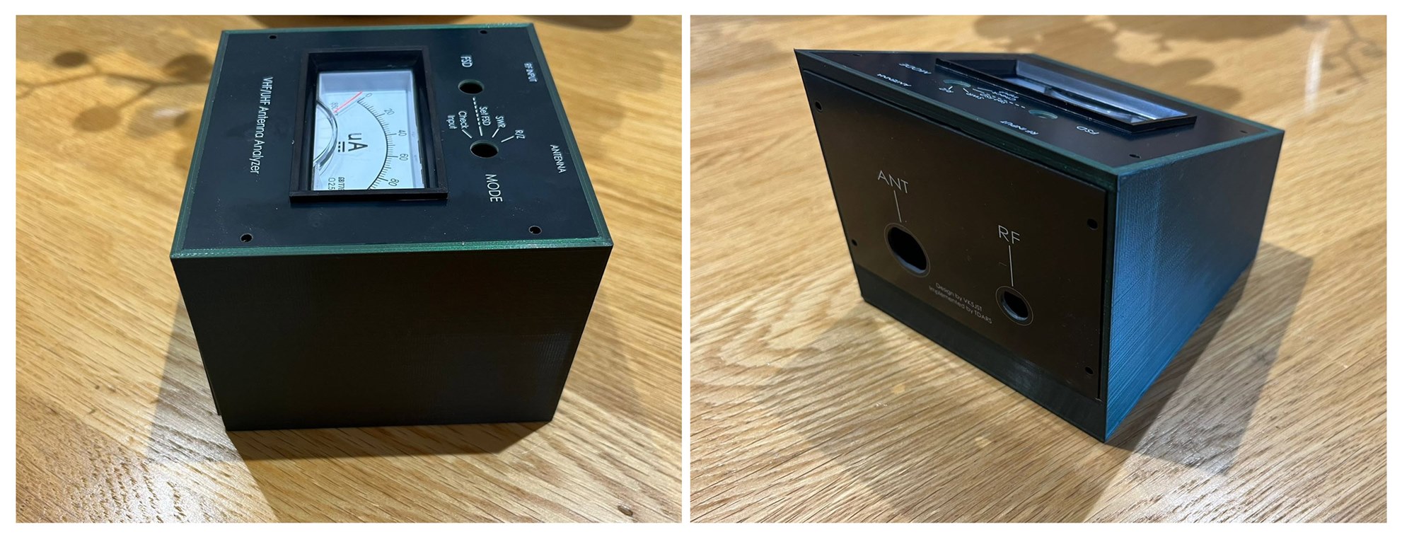
The left one is box-shaped, whereas the right one has a sloped top. The 3D files for both of these designs are downloadable (box shape, and sloped top version).
Obtain a Kit of Parts
The first step, is to obtain a kit of parts. Only five kits were produced, but, if you don’t have a kit and want one, then it’s possible to create your own kit.
To do that, for the printed circuit boards (PCBs), go to the GitHub page for the project, and download the PCB zip files, and upload them to any PCB manufacturer website. All step-by-step instructions on how to do that are documented at the GitHub page.
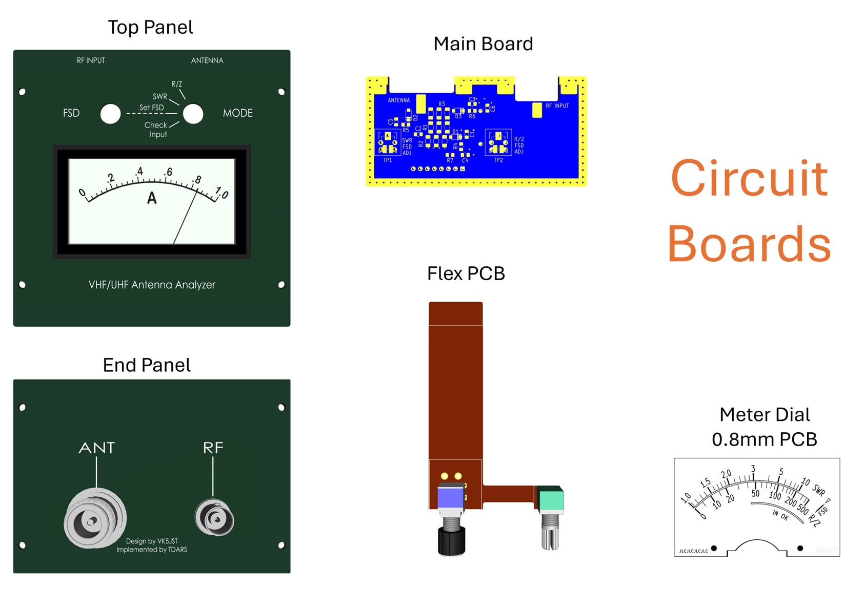
There are a lot of boards. The only mandatory one is the main board, but the other boards will help simplify construction, almost eliminating the need to drill any holes or making many wired connections.
For the components, check the parts list at the GitHub page (scroll to near the bottom of the page), and order the bits and pieces. Most parts are available from any decent electronics distributor, however, a few parts (particularly the panel meter) are only available from AliExpress.
Circuit Diagram

Building an Enclosure
For this project, it’s best to start off with the enclosure if possible.
If you wish to 3D print an enclosure, download the style V1 (box shape) or style V3 (sloped top) files. These were designed by Paul M0PLA.

All the dimensions are at the GitHub page, if you fancy creating your own design.
Alternatively, you could always purchase an off-the-shelf larger case, and drill holes in it to accommodate things; there are some nice examples of this in the photos further below.
Flex PCB Construction
This project uses (optionally) a flexible PCB. It is possible to construct the antenna analyzer without it, but it simplifies things, and almost entirely eliminates all point-to-point wiring in the project, save two wires to the panel meter.
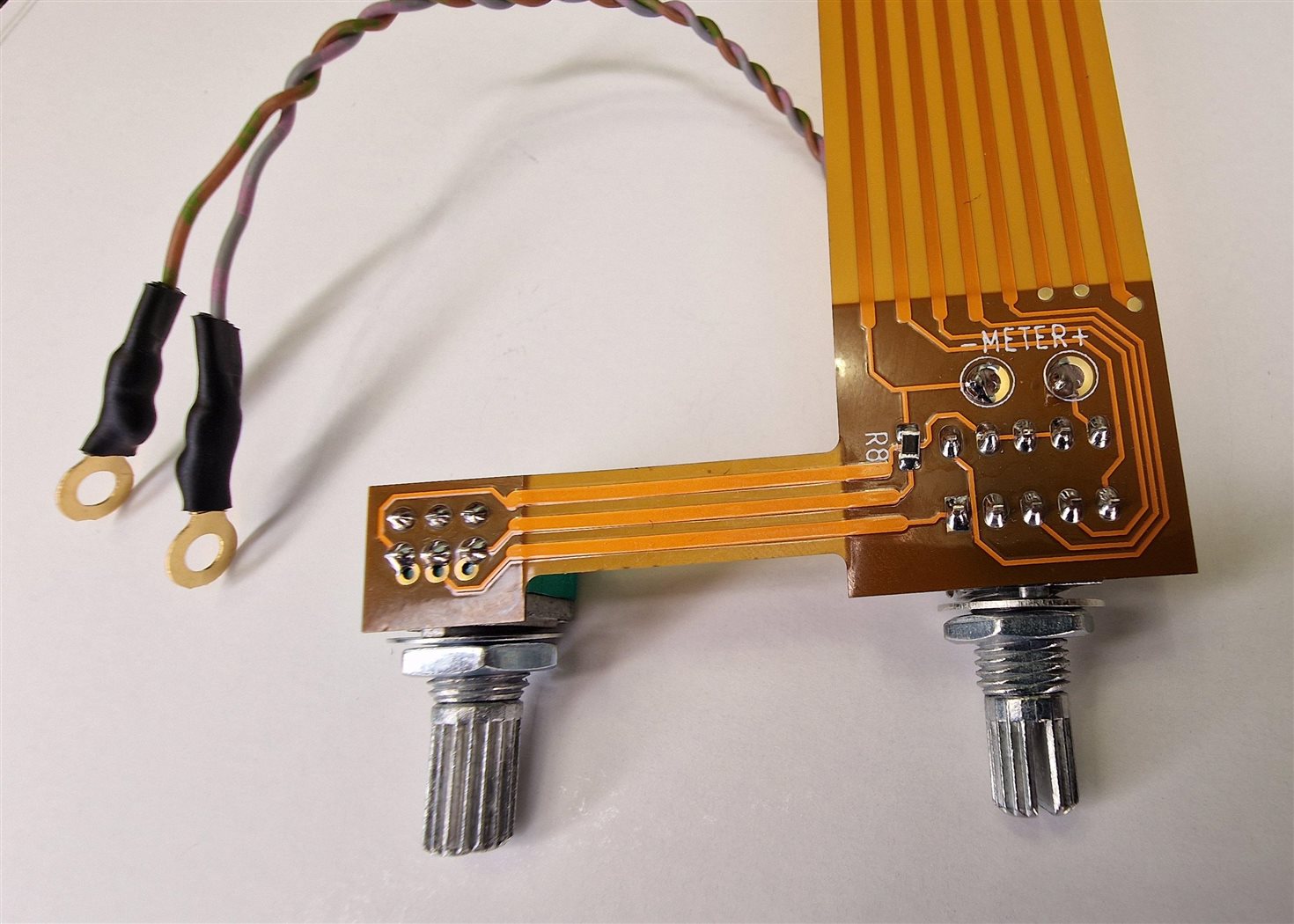
The flex PCB is used for all the top panel components, and connects back to the main PCB. After it was soldered up, I used epoxy glue to secure the rotary components to the top panel.

Panel Meter
The panel meter comes with a black bezel that unclips, and then the clear cover and aluminium meter dial plate were removed, and a paper dial was glued onto the plate and replaced back.
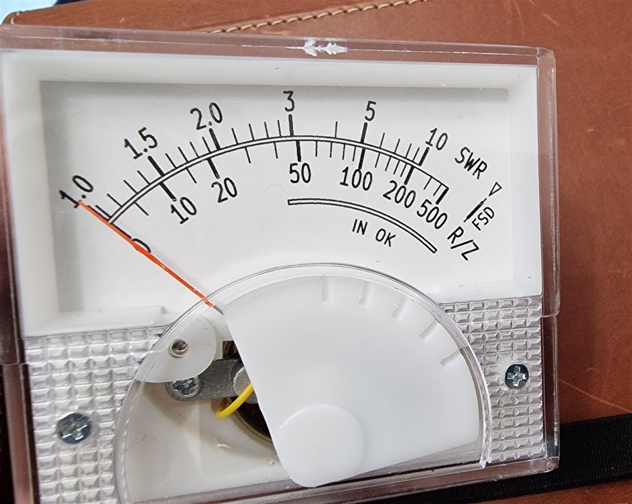
Optionally, a 0.8 mm thick PCB meter dial could be used instead of a paper one; for instance, PCB manufacturers offer a 0.8 mm thick aluminium PCB service, which would work.
Slide the meter into the top panel, and and then add the two supplied side ears and rotate to fix the meter in position.

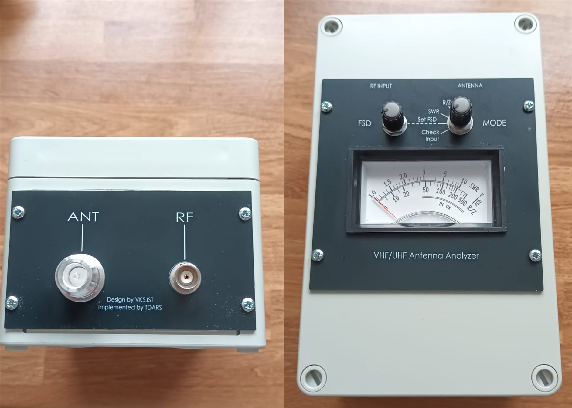
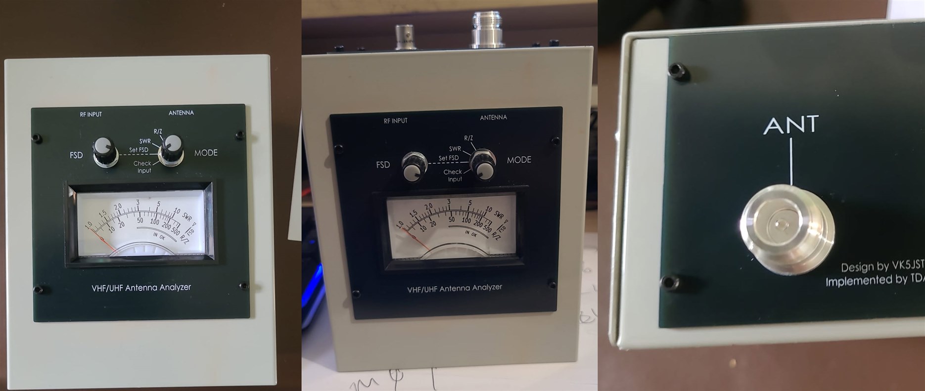
Here’s the front panel screwed into the enclosure:
End Panel RF Connector Assembly
The end panel assembly is quick to construct; it only houses two RF connectors. One connector is attached to an RF signal source (such as a radio transmitter; 2W max, unless you’ve attached an attenuator inline), and the other end attaches to the antenna being analyzed. Solder the ring tags as shown in the photo, and it’s done! Don’t screw it into the enclosure yet.

Main Board Parts Soldering
The main board houses nearly all the remainder components. There are two things to do (in this order):
• Solder the surface-mount devices (SMDs)
• Solder the two trimmer potentiometers, and a labeled wire link on the underside of the board
If you’re using a prepared kit of parts, there may be some spares SMDs, just in case some go missing. If you find parts are pinging off into the air, it’s because of the tweezer quality. I find 1mm flat-ended tweezers work best for me, but they are more pricey than pointed tweezers.

Once you’re done with the SMDs and trimmer potentiometers (and don't forget the wire link indicated on the underside of the board!), you’re ready to join the two constructed boards as described next.
Joining the End Panel and Main Board
I used Blu-Tack to temporarily hold the two boards together as perpendicular as possible, and then I soldered the RF connector center pins.
Next, using a powerful soldering iron, solder the main board edge onto the end panel. Do this on both sides of the main board.
The construction will be more rigid now, but it’s still best to be gentle with it. Afterwards, you can see in the photo that I applied some epoxy glue onto the connector nuts, to prevent them loosening and rotating.

Attaching the End Panel/Main Board Assembly to the Enclosure
Carefully insert the flexible PCB into the main PCB connector. Then, screw on the end panel to the enclosure!
All of the electronics assembly is now complete!

Next Steps
A one-time alignment is required, which doesn’t need any special equipment if you already have a HF transmitter that supports adjustable power output up to 2W max (use an attenuator if required!).
All the steps for the alignment are detailed on the antenna analyzer GitHub page. Alfter that, the project is ready to use! A couple of these antenna analyzers are already aligned and in use, I have yet to perform the alignment on mine.
Here’s a photo of a complete antenna analyzer, that has been calibrated and is in use. This one was constructed by M7FZG, fitted in a plastic enclosure:
Here's a version built into a folded metal enclosure, by M0PNN:
In my case, for the alignment, I will probably use a signal generator, a cheap RF amplifier, an attenuator, and an oscilloscope.
Summary
The antenna analyzer that was described here is extremely easy to construct and straightforward to use.
It would be great to hear about people’s experiences with either this, or other antenna analyzers, and any tips/suggestions!
Thanks for reading.


