Table of Contents
Introduction
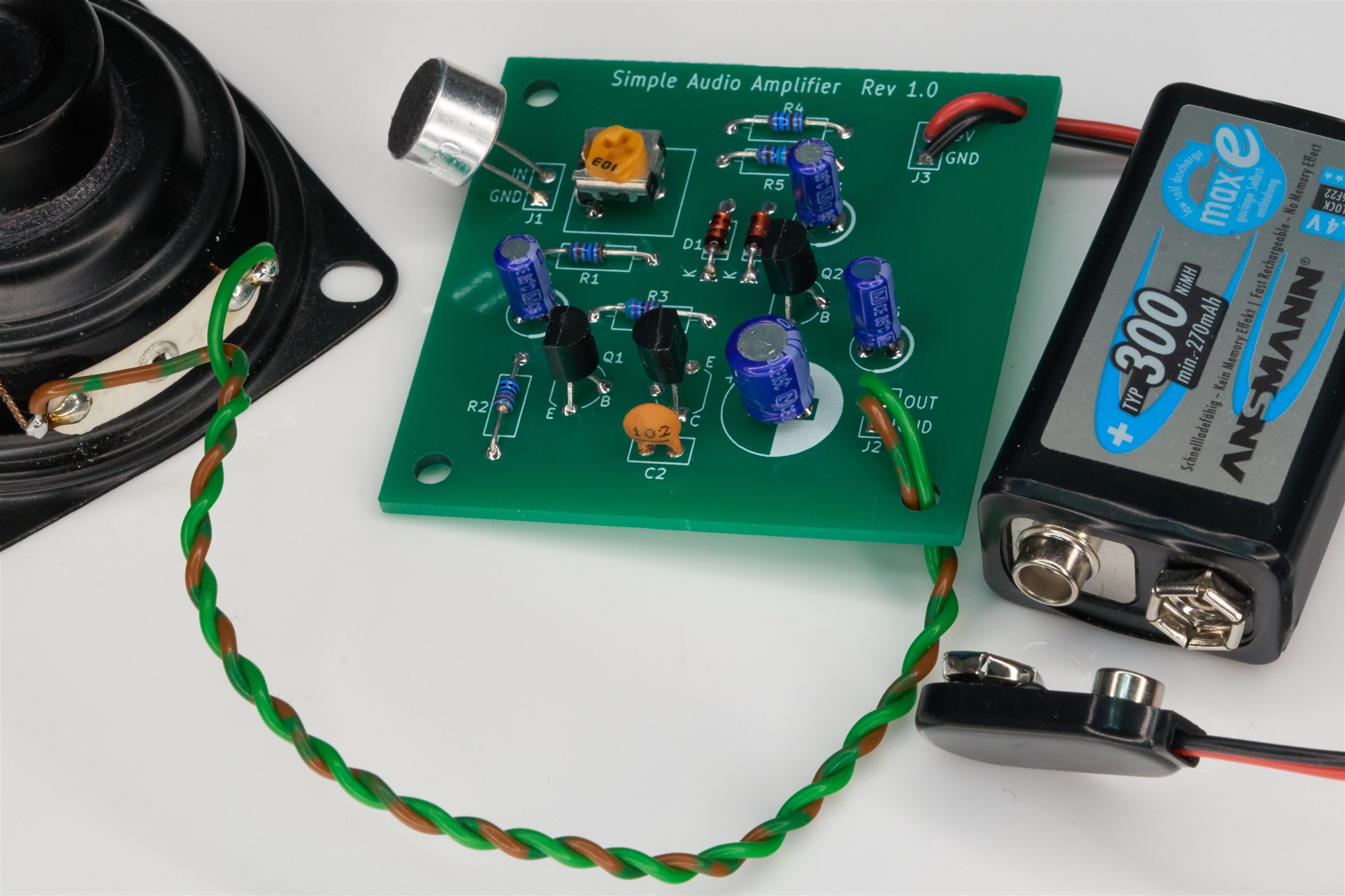
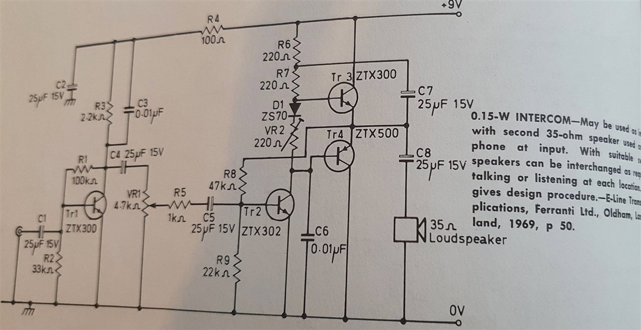
A while back I built a little audio amplifier based on a circuit found in an old book.
The amplifier performed reasonably OK (by that I mean adequate for speech, it's not hi-fi!), considering how simple the circuit was.
This blog post discusses the design. I think it is a nice beginner project because it can be assembled within half an hour. I prepared some documentation for this project because it is intended to be used for soldering practice. I think kids may enjoy this project too, because they can use it as a wired listening device or intercom.

How Does it Work?
The original circuit is shown below (image source: my photo, but it's from this book):

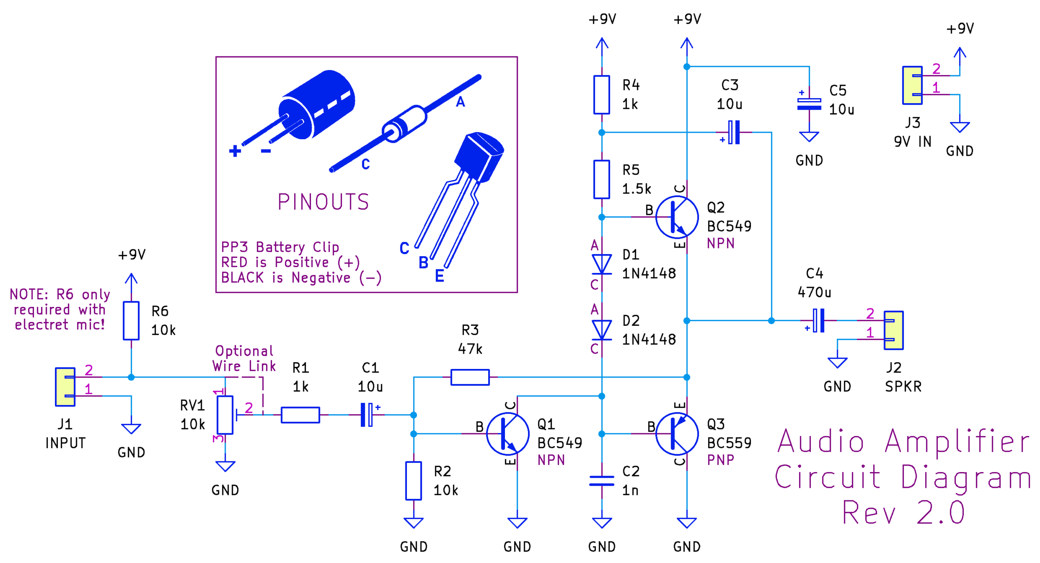
My circuit is slightly cut down, missing the first stage, and has a few tweaks.

Looking at the circuit from right-to-left, the two totem-pole transistors Q2 and Q3 operate in a push-pull arrangement, to drive the output high or low; these two transistors provide the current gain for the amplifier.
You don’t want the two transistors to ever be in a situation where they are not conducting somewhat, because that would cause distortion.
The two diodes ensure there’s always 1.2V of difference between the base voltages for both output transistors, and this is used to ensure that both transistors are always slightly conducting. For instance, if the output happens to be at 4V, then the top transistor base voltage has to be around 4.6V, and that means that the lower transistor voltage has to be about 3.4V (two diode drops); that ensures that the lower transistor is conducting too.
Capacitor C3 is interesting; it is used to provide extra bias to the top transistor so that the output voltage can swing higher when needed; the way it works is that if you assume C3 has charged to some voltage level, then when the output swings high, the left side of C3 has to swing high too, and that turns on the transistor harder. C3 is known as a bootstrap capacitor.
The lower transistor doesn’t have such a bootstrap capacitor; it doesn’t need the extra help in turning on, since transistor Q1 can relatively easily pull the base of Q3 low.
The purpose of transistor Q1 is to perform as a common-emitter amplifier, providing voltage gain for the overall amplifier circuit. Resistor R3 provides negative feedback for this combined circuit.
On the input side, if you don't have a variable resistor (RV1), you can replace it with a wire link. Resistor R6 provides some current to power an electret mic element (if fitted). If you're using some other audio source, then R6 is not required.
Building It
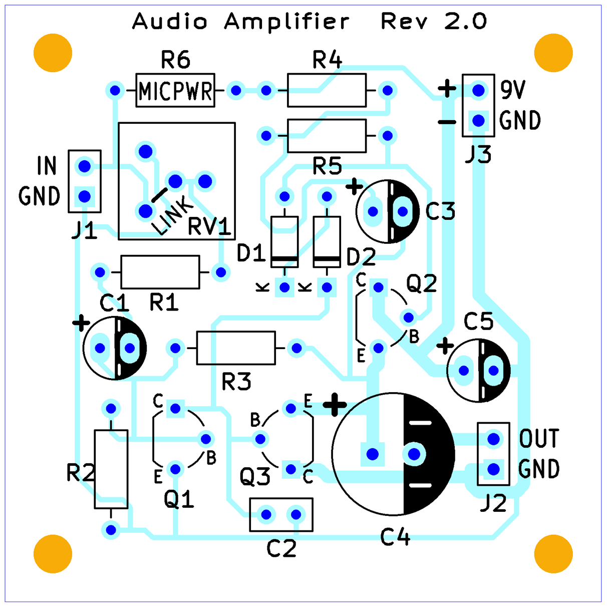
If you wish to build the circuit, download the Gerber zip file and upload it to any PCB manufacturer; it will cost about $2 plus shipping, for five boards.

To make life easier, there’s a PDF audio amplifier assembly guide containing the bill-of-materials, and all detail needed to construct the circuit.
Using It
I connected an 8-ohm speaker to the output (ideally, a higher impedance speaker is preferred, but that was all I had), and wired an electret mic element to the input side. It makes a nice crude one-way intercom / field telephone if you extend the speaker using a load of thin speaker wire or bell wire.
I didn’t perform any other tests (I have measured its distortion in the past; the circuit can achieve a level of 0.2% THD, although that is very dependent on a specific audio input level.
Summary
A very simple, jellybean-component audio amplifier can be constructed within about half an hour and then used as a one-directional intercom, or for general experimenting, because an audio amplifier can have lots of uses. It's also a good candidate circuit for trying out various bits of test equipment.
It could be useful as a beginner project; all parts are low-cost and through-hole.
To build the circuit, see the PDF assembly guide, and upload the Gerber files to any PCB manufacturer.
Thanks for reading!

Top Comments