element14 Community
element14 Community
    Register Log In
  • Site
  • Search
  • Log In Register
  • About Us
  • Community Hub
    Community Hub
    • What's New on element14
    • Feedback and Support
    • Benefits of Membership
    • Personal Blogs
    • Members Area
    • Achievement Levels
  • Learn
    Learn
    • Ask an Expert
    • eBooks
    • element14 presents
    • Learning Center
    • Tech Spotlight
    • STEM Academy
    • Webinars, Training and Events
    • Learning Groups
  • Technologies
    Technologies
    • 3D Printing
    • FPGA
    • Industrial Automation
    • Internet of Things
    • Power & Energy
    • Sensors
    • Technology Groups
  • Challenges & Projects
    Challenges & Projects
    • Design Challenges
    • element14 presents Projects
    • Project14
    • Arduino Projects
    • Raspberry Pi Projects
    • Project Groups
  • Products
    Products
    • Arduino
    • Avnet Boards Community
    • Dev Tools
    • Manufacturers
    • Multicomp Pro
    • Product Groups
    • Raspberry Pi
    • RoadTests & Reviews
  • Store
    Store
    • Visit Your Store
    • Choose another store...
      • Europe
      •  Austria (German)
      •  Belgium (Dutch, French)
      •  Bulgaria (Bulgarian)
      •  Czech Republic (Czech)
      •  Denmark (Danish)
      •  Estonia (Estonian)
      •  Finland (Finnish)
      •  France (French)
      •  Germany (German)
      •  Hungary (Hungarian)
      •  Ireland
      •  Israel
      •  Italy (Italian)
      •  Latvia (Latvian)
      •  
      •  Lithuania (Lithuanian)
      •  Netherlands (Dutch)
      •  Norway (Norwegian)
      •  Poland (Polish)
      •  Portugal (Portuguese)
      •  Romania (Romanian)
      •  Russia (Russian)
      •  Slovakia (Slovak)
      •  Slovenia (Slovenian)
      •  Spain (Spanish)
      •  Sweden (Swedish)
      •  Switzerland(German, French)
      •  Turkey (Turkish)
      •  United Kingdom
      • Asia Pacific
      •  Australia
      •  China
      •  Hong Kong
      •  India
      •  Korea (Korean)
      •  Malaysia
      •  New Zealand
      •  Philippines
      •  Singapore
      •  Taiwan
      •  Thailand (Thai)
      • Americas
      •  Brazil (Portuguese)
      •  Canada
      •  Mexico (Spanish)
      •  United States
      Can't find the country/region you're looking for? Visit our export site or find a local distributor.
  • Translate
  • Profile
  • Settings
Open Source Hardware
  • Technologies
  • More
Open Source Hardware
Blog Half-Hour Project: Building a Simple Audio Amplifier
  • Blog
  • Forum
  • Documents
  • Events
  • Polls
  • Members
  • Mentions
  • Sub-Groups
  • Tags
  • More
  • Cancel
  • New
Join Open Source Hardware to participate - click to join for free!
  • Share
  • More
  • Cancel
Group Actions
  • Group RSS
  • More
  • Cancel
Engagement
  • Author Author: shabaz
  • Date Created: 5 Mar 2025 1:29 AM Date Created
  • Views 7354 views
  • Likes 9 likes
  • Comments 17 comments
  • microphone
  • audio
  • audio amplifier
  • microphone amplifier
  • amplifier
  • loudspeaker
  • mic
  • beginners
  • audio amplification
  • speaker
  • beginner
Related
Recommended

Half-Hour Project: Building a Simple Audio Amplifier

shabaz
shabaz
5 Mar 2025

Table of Contents

  • Introduction
  • How Does it Work?
  • Building It
  • Using It
  • Summary

Introduction

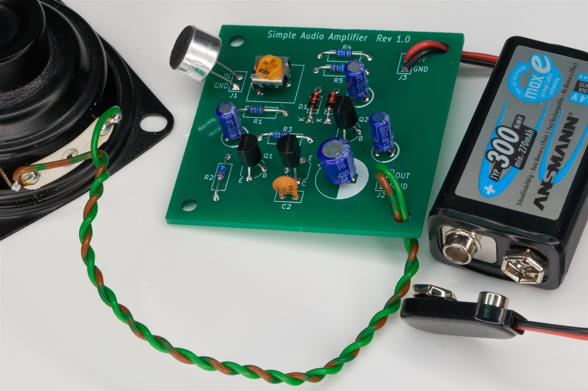
A while back I built a little audio amplifier based on a circuit found in an old book.

The amplifier performed reasonably OK (by that I mean adequate for speech, it's not hi-fi!), considering how simple the circuit was.

This blog post discusses the design. I think it is a nice beginner project because it can be assembled within half an hour. I prepared some documentation for this project because it is intended to be used for soldering practice. I think kids may enjoy this project too, because they can use it as a wired listening device or intercom.

image

How Does it Work?

The original circuit is shown below (image source: my photo, but it's from this book):

image

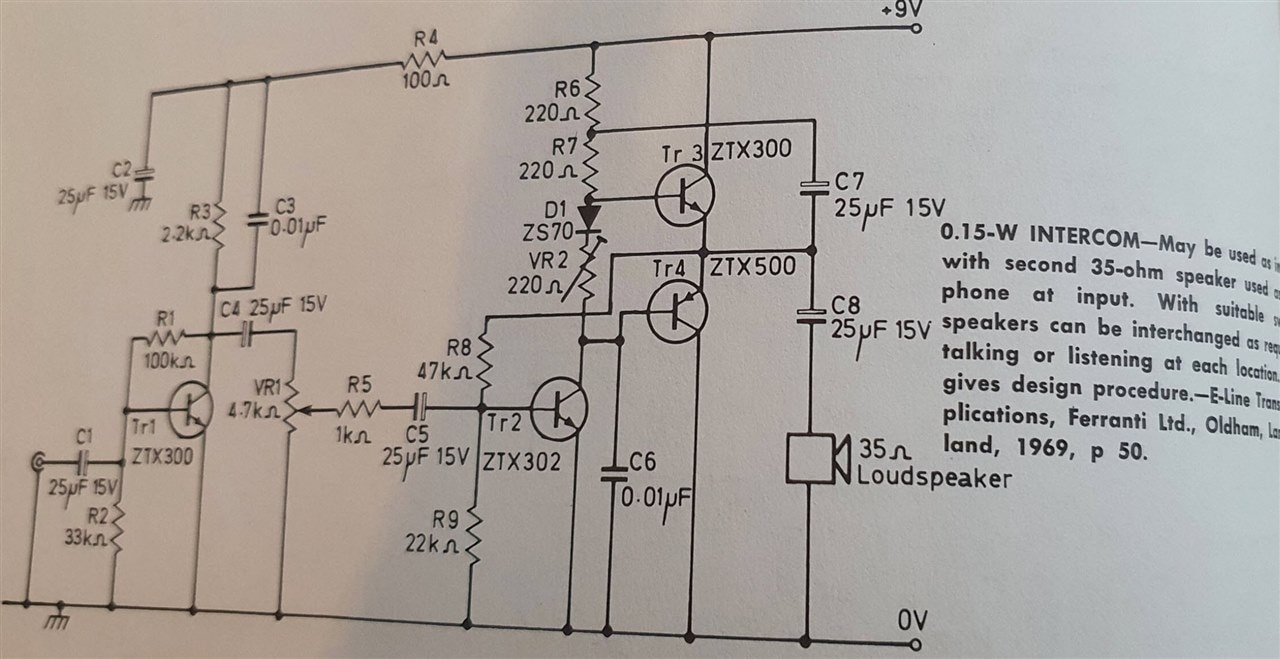
My circuit is slightly cut down, missing the first stage, and has a few tweaks.

image

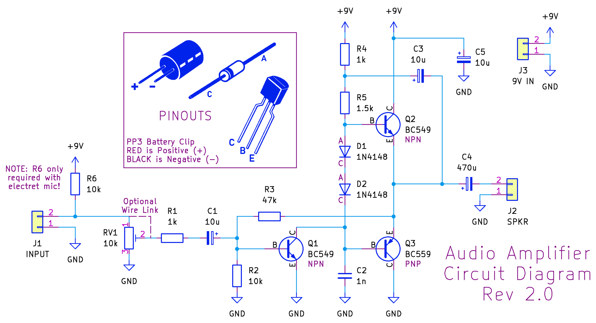
Looking at the circuit from right-to-left, the two totem-pole transistors Q2 and Q3 operate in a push-pull arrangement, to drive the output high or low; these two transistors provide the current gain for the amplifier.

You don’t want the two transistors to ever be in a situation where they are not conducting somewhat, because that would cause distortion.

The two diodes ensure there’s always 1.2V of difference between the base voltages for both output transistors, and this is used to ensure that both transistors are always slightly conducting. For instance, if the output happens to be at 4V, then the top transistor base voltage has to be around 4.6V, and that means that the lower transistor voltage has to be about 3.4V (two diode drops); that ensures that the lower transistor is conducting too.

Capacitor C3 is interesting; it is used to provide extra bias to the top transistor so that the output voltage can swing higher when needed; the way it works is that if you assume C3 has charged to some voltage level, then when the output swings high, the left side of C3 has to swing high too, and that turns on the transistor harder. C3 is known as a bootstrap capacitor.

The lower transistor doesn’t have such a bootstrap capacitor; it doesn’t need the extra help in turning on, since transistor Q1 can relatively easily pull the base of Q3 low.

The purpose of transistor Q1 is to perform as a common-emitter amplifier, providing voltage gain for the overall amplifier circuit. Resistor R3 provides negative feedback for this combined circuit.

On the input side, if you don't have a variable resistor (RV1), you can replace it with a wire link. Resistor R6 provides some current to power an electret mic element (if fitted). If you're using some other audio source, then R6 is not required.

Building It

If you wish to build the circuit, download the Gerber zip file and upload it to any PCB manufacturer; it will cost about $2 plus shipping, for five boards.

image


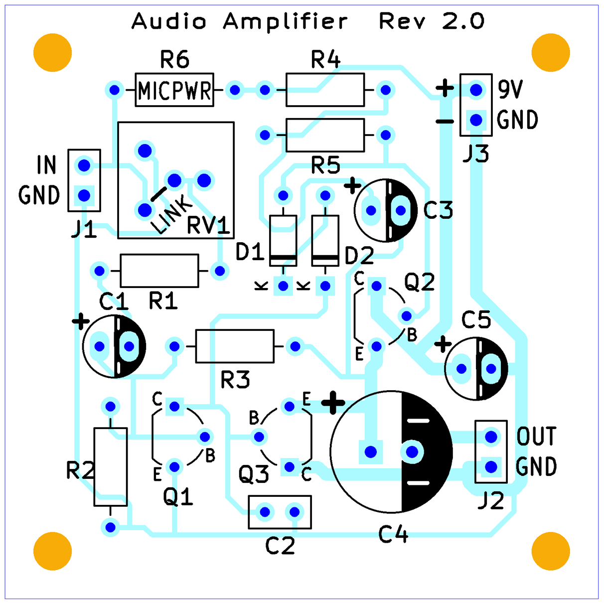
To make life easier, there’s a PDF audio amplifier assembly guide containing the bill-of-materials, and all detail needed to construct the circuit.

Using It

I connected an 8-ohm speaker to the output (ideally, a higher impedance speaker is preferred, but that was all I had), and wired an electret mic element to the input side. It makes a nice crude one-way intercom / field telephone if you extend the speaker using a load of thin speaker wire or bell wire.

I didn’t perform any other tests (I have measured its distortion in the past; the circuit can achieve a level of 0.2% THD, although that is very dependent on a specific audio input level.

Summary

A very simple, jellybean-component audio amplifier can be constructed within about half an hour and then used as a one-directional intercom, or for general experimenting, because an audio amplifier can have lots of uses. It's also a good candidate circuit for trying out various bits of test equipment.

It could be useful as a beginner project; all parts are low-cost and through-hole.

To build the circuit, see the PDF assembly guide, and upload the Gerber files to any PCB manufacturer.

Thanks for reading!

  • Sign in to reply
Parents
  • jc2048
    jc2048 6 months ago

    Nice small project.

    Just for reference, this is the original from the Ferranti Applications Manual. The version in your book is a straightforward copy.

    image


    This is the spec they give. With the 25uF caps, the low end frequency performance isn't that good, but it didn't need to be for an intercom. The distortion didn't matter too much, either, provided you could readily understand what was being said.

    image


    The bootstrap is interesting and crops up in a couple of the other circuits in the manual (a 2W amplifier, and a preamp, where it lifts the input impedance). This is the preamp (they claim a measured 5M input impedance for that)

    image


    If you'd asked me to explain the bootstrapping (in your circuit), I'd have described it as turning the resistor (R5) into a better approximation to a current source (only for ac, obviously) - the cap lifts the voltage at the top of the resistor by almost the same amount as the bottom moves up, leading to the resistor maintaining the current as the voltage at the base of the output transistor goes up. That keeps things balanced against the transistor (Q1) collector which very much behaves like a current sink. Essentially, the same as what you're saying, just in slightly different terms.

    • Cancel
    • Vote Up 0 Vote Down
    • Sign in to reply
    • More
    • Cancel
  • shabaz
    shabaz 6 months ago in reply to jc2048

    Thank you for this! It's great to finally see the detail about the original circuit. And great explanation about the bootstrap portion.

    I hadn't realized they had a separate preamp, I'd been experimenting with attaching my own 1-transistor amp.

    image

    I was initially thinking of doing half-duplex, but then starting thinking how neat it could be to have a phone 'hybrid' transformer.. but those are quite impractical to obtain, so I googled around, and saw a 1-transistor unbalanced-to-balanced circuit, followed by a resistors as a mixer, would be effectively the same thing! So I've inserted that in-between the preamp and the main amp in this circuit diagram:

    image

    It's not a brilliant circuit, but figured it could be fun to try. I might build this up, in my next PCB order.

    It would be neat to have some sort of alert (maybe just an LED that lights up) to tell the other side to switch on their unit, but I'm not sure how to best do that. Maybe pull the wire low and detect that somehow. Or, a bit like a real telephone, put a higher AC voltage on it, so it can generate an audible alert.. small transformers are cheap, but that's getting more complicated, the circuit is already getting quite large due to sticking with transistors and no ICs!

    • Cancel
    • Vote Up 0 Vote Down
    • Sign in to reply
    • More
    • Cancel
  • Jan Cumps
    Jan Cumps 6 months ago in reply to shabaz

    After you posted this circuit, I was thinking about setting up the end stage, and then probe that bootstrap circuit. I think that I can visualise in my brain what it's doing. But would be great to see that on an oscilloscope.

    • Cancel
    • Vote Up 0 Vote Down
    • Sign in to reply
    • More
    • Cancel
Comment
  • Jan Cumps
    Jan Cumps 6 months ago in reply to shabaz

    After you posted this circuit, I was thinking about setting up the end stage, and then probe that bootstrap circuit. I think that I can visualise in my brain what it's doing. But would be great to see that on an oscilloscope.

    • Cancel
    • Vote Up 0 Vote Down
    • Sign in to reply
    • More
    • Cancel
Children
  • shabaz
    shabaz 6 months ago in reply to Jan Cumps

    Hi! Good idea, I'll try to capture some traces.

    • Cancel
    • Vote Up 0 Vote Down
    • Sign in to reply
    • More
    • Cancel
  • shabaz
    shabaz 6 months ago in reply to Jan Cumps

    Here's the results..

    I disconnected the electret mic (and removed the resistor that passed power to it) and also disconnected the speaker.

    The circuit was powered from a rechargeable 9V battery, and its terminal voltage was about 8.8V. 

    I fed a 100mVp-p 1kHz sine wave on the input, with the trimmer resistor on the board set fully clockwise, i.e. maximum gain.

    I used a couple of X10 probes, hooked up to two points:

    The yellow trace is the output where the speaker would normally connect, i.e. pin 2 of J2.

    The green trace is the left side of the bootstrap capacitor C3, i.e. the junction of C3/R4/R5.

    The peaks of the green trace are 9.3V, i.e. higher than the battery terminal voltage.

    image

    If I remove C3, the result is as follows; you can see that the green trace (R4/R5 junction) now no longer reaches the high voltage:

    image

    Although the output yellow trace visually looks vaguely the same, the spectrum view shows the distortion very easily (see the values of the fundamental and harmonics in the table on the right side of the screenshots.

    • Cancel
    • Vote Up 0 Vote Down
    • Sign in to reply
    • More
    • Cancel
element14 Community

element14 is the first online community specifically for engineers. Connect with your peers and get expert answers to your questions.

  • Members
  • Learn
  • Technologies
  • Challenges & Projects
  • Products
  • Store
  • About Us
  • Feedback & Support
  • FAQs
  • Terms of Use
  • Privacy Policy
  • Legal and Copyright Notices
  • Sitemap
  • Cookies

An Avnet Company © 2025 Premier Farnell Limited. All Rights Reserved.

Premier Farnell Ltd, registered in England and Wales (no 00876412), registered office: Farnell House, Forge Lane, Leeds LS12 2NE.

ICP 备案号 10220084.

Follow element14

  • X
  • Facebook
  • linkedin
  • YouTube