


Table of Contents
Introduction
There’s a simple, discrete-component amateur radio receiver project out there, which (as I understand) started life as a design by an amateur radio enthusiast called Ashar Farhan, and then it was further developed and evolved into a Thomas Jefferson High School project, and then it was further popularised by a YouTube presenter by the handle of SolderSmoke. I’m not too familiar with all this history, but Problemchild is more aware of it than I am.
The receiver is intended to be tuned to a band at around 7 MHz; this is a popular licensed band for amateur radio enthusiasts.
Hundreds (thousands?) of people built the various iterations of the project over time; they were mostly DIY’d onto sheets of copper-clad board. Some of the results look amazing; it takes lots of care and dedication to assemble like that and get it all working. As part of a radio group that I'm a member of, it was decided to port the design into a KiCad project and try to build from there. Admittedly, some of the charm will be lost when assembling from a printed circuit board (PCB), but KiCad is what I'm familiar with, so, for me at least, I wanted to use it.
That was almost a year ago. I didn’t have time to make much progress. I figured I need to make little bits of time here and there to work my way through it. This first blog post covers a small part of the project.
How Does It Work?
This project is in some ways self-documenting : ) The printed circuit board (PCB) has a silkscreen on it, which shows all the building blocks and how they are attached. The topology is known as a Direct Conversion Receiver.

How to Build It?
I created a GitHub repository called simple_dcr containing the PCB source files, and the Gerber files, so that circuit boards can be ordered from any PCB manufacturer. The GitHub page lists all the parts needed to assemble the board.
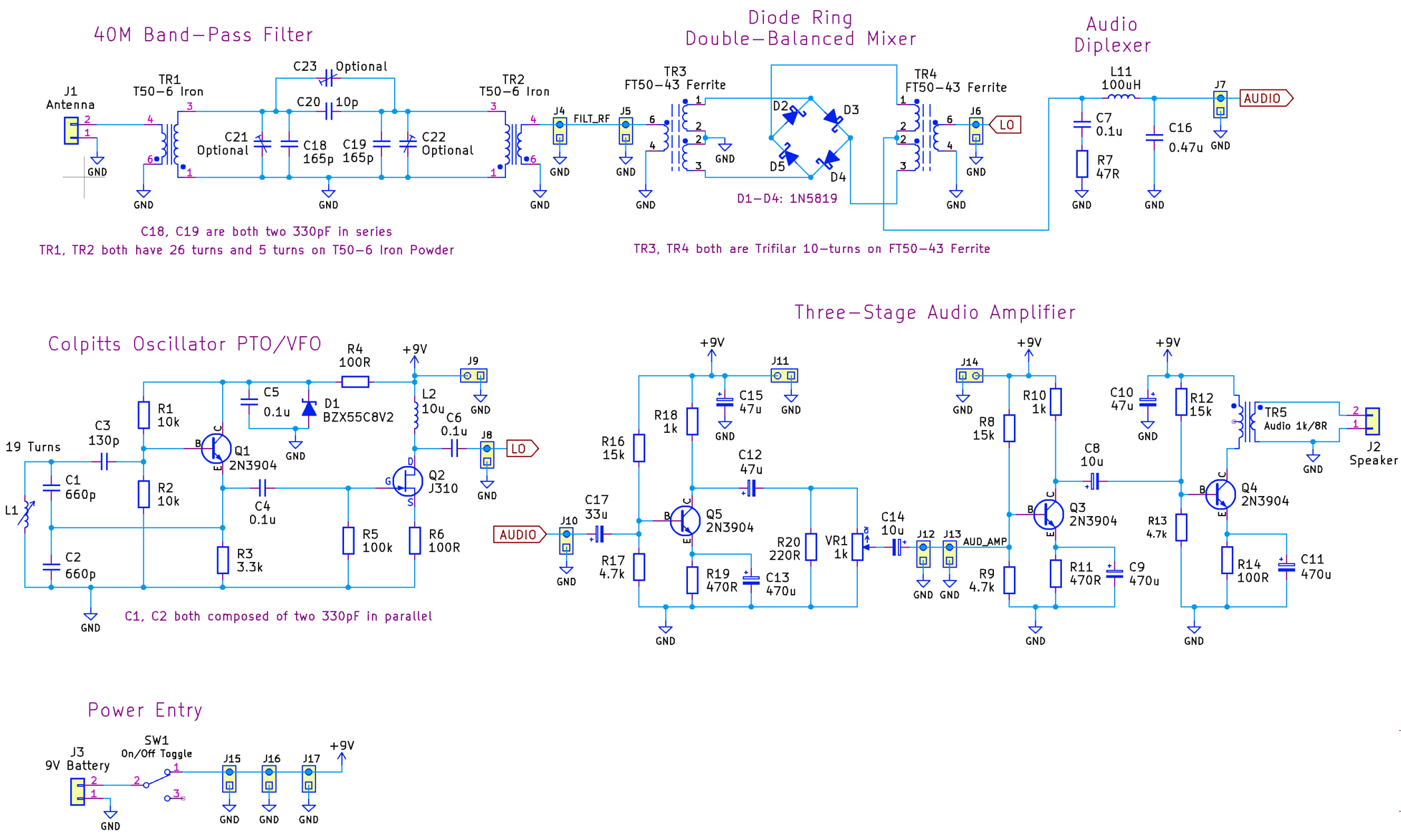
Circuit Diagram
Consult the GitHub repo for the latest circuit diagram in case it ever changes, but the first revision circuit is reproduced here.
What Has Been Constructed So Far?
I have not done a lot! Meanwhile, the rest of the radio group has been busy testing the circuit on copper-clad boards, so everyone has more experience with the circuit than I do. I made a start on the band-pass filter and the mixer almost a year ago. I have constructed the third stage of the audio amplifier, i.e. just transistor Q4 and the associated passives (R12, R13, R14, C8, C10, C11 and TR5.
Audio Amplifier
The entire audio amplifier circuit stinks. To be fair, it was never intended to be of good quality; as I understand, it was just a quick hack by someone, intended to be improved at a later date, and I'm guessing it was also deliberately intended to encourage people to experiment and improve upon the almost-minimal-viable circuit. The amplifier uses a cheap transformer in the third stage (the first stage is labelled Audio Preamp in the block diagram, and the second and third stages together are labelled Audio Amp), as found in 1970’s pocket transistor radios. These transformers are available from AliExpress.
If it were me, personally, I’d replace the circuit with an audio amplifier integrated circuit (IC), but that’s probably not in the spirit of the design of this radio, since I believe it was deliberately intended to be entirely discrete. Nevertheless, you’ll notice that the PCB can be snapped into pieces, or traces can be cut, and perforated prototyping boards can be piggy-backed on top, with custom modules if desired. I think it would be worth doing that for the audio amplifier one day, but I wanted to build the circuit as it stands for now.
Testing the Amplifier’s Third Stage
As mentioned, the third stage consists of Q4 and its closest passive components, including the transformer. For this first test, R12 was 56k, and R13 was 10k (which was later discovered to have resulted in very little quiescent current through the transistor).
I fed a 1 kHz tone into the input (the left side of capacitor C8). At the output, I attached an 8 ohm resistor instead of a speaker, and then attached the ‘scope probe across the resistor.
I powered the circuit from a power supply set to 8.5 V (since that may be a plausible voltage from a PP3 battery at some point in its life).
In the photograph, the red/black wires at the top are connected to 8.5 V, the purple wire is the third stage input (connected to a signal generator), blue is ground, and the two gray wires at the right are attached to an 8 ohm resistor.

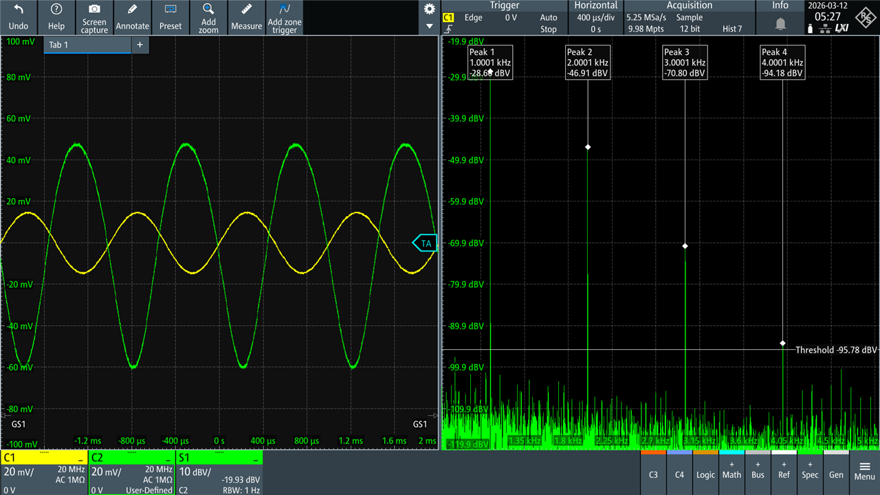
The screenshot below shows the input 1 kHz signal in yellow, and the output in green. In this screenshot, the input voltage is 30 mV peak-to-peak (p-p) and the output is about 105 mV p-p. That’s not a lot of power! Enough to be audible in a very quiet room, perhaps.
Why did I pick 30 mV p-p for the input? That’s simply because much higher than that, and the distortion gets worse. In reality, a lot of distortion isn’t a showstopper, because the amplifier is not intended for music; it’s for tones or speech.
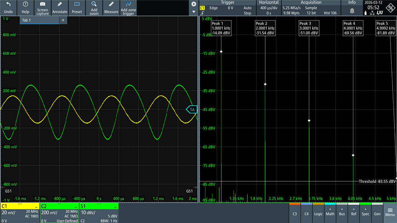
Here’s what happens when the input is increased to 100 mV p-p; tons of distortion, but probably usable in a pinch; it's amazing what the ear can choose to ignore when listening to speech:
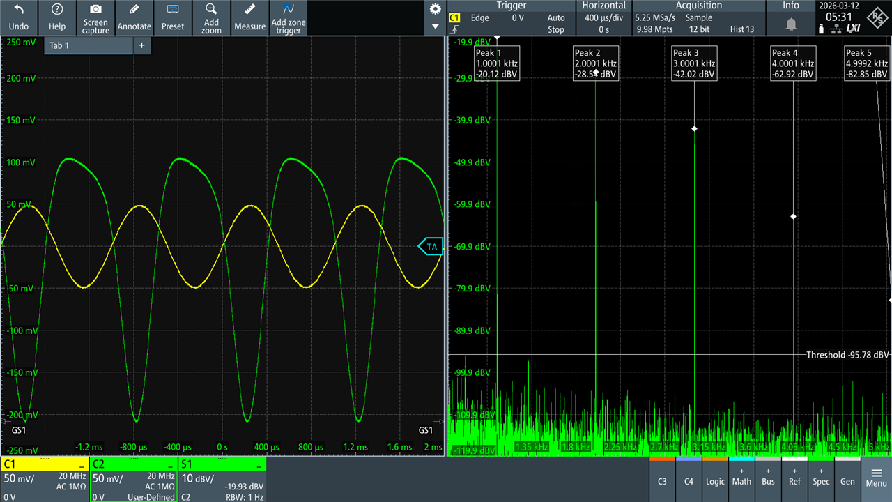
Incidentally, the spectrum views to the right of the screenshots show a span of 5 kHz. You can see the fundamental (1 kHz) and some of the harmonics.
The amplitudes are in dBV, which can be converted to V p-p using the formula Vpp = 2.28 × 10^ (dBV/20). Example: -20 dBV corresponds to 2.28 x 10^(-1), which is 2.28 x 0.1 = 0.228 Vp-p.
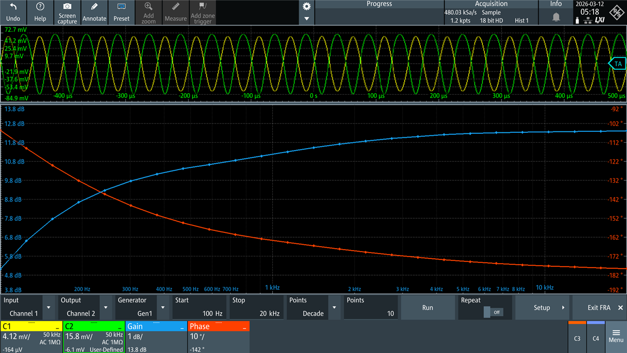
I decided to plot the frequency response of the amplifier third stage, for 100 Hz to 20 kHz (in reality we only really care for speech at about 300 Hz to 3 kHz I expect).
I was curious what the change would be if the 8 ohm load was replaced with 64 ohm, because 64 ohm speakers are feasible to purchase.
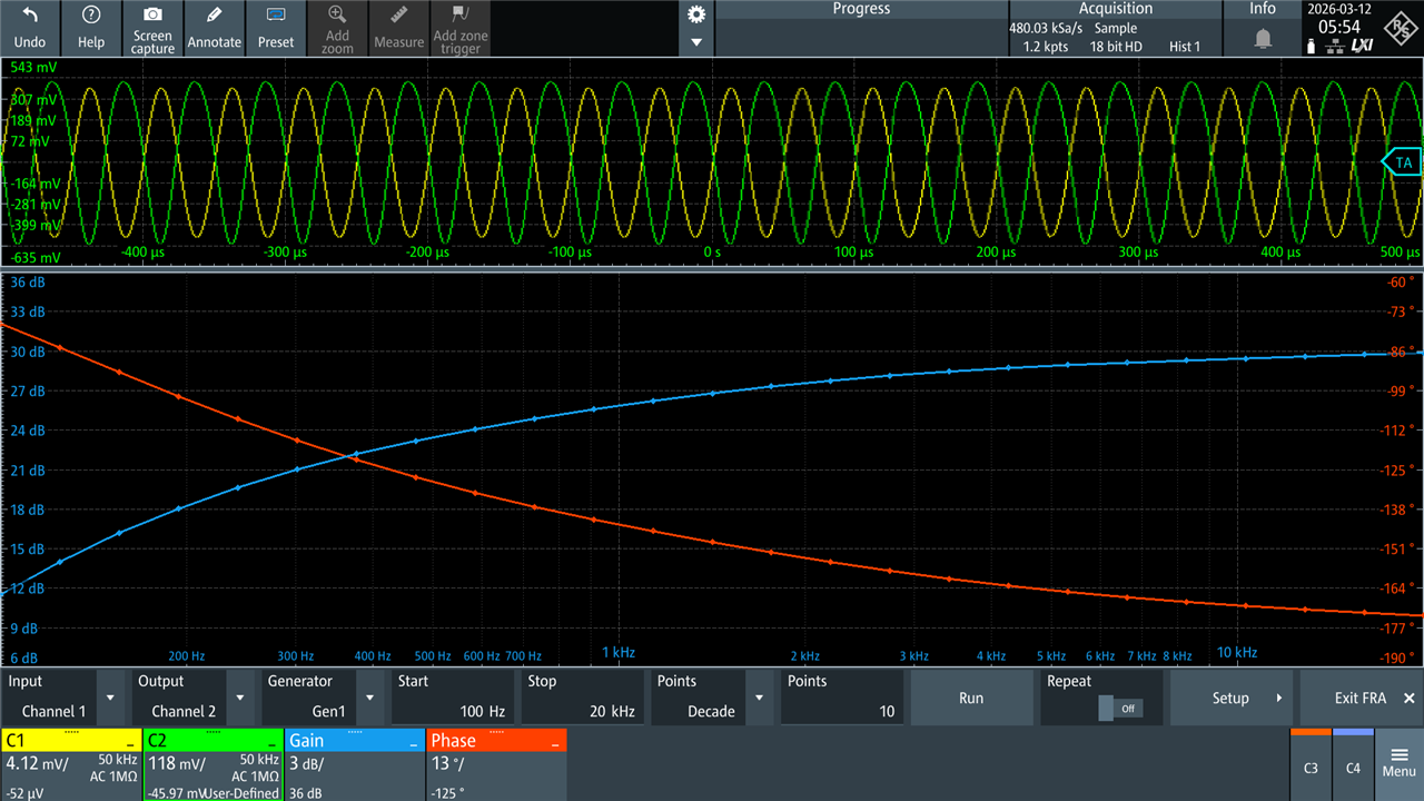
The screenshot below shows the result with a 64 ohm load and an input of 30 mV p-p. The yellow input is shown at 20 mV per division on the oscilloscope, and the green output is shown at 200 mV per division.
Just for completeness, here is the frequency response with the 64 ohm load:
After these experiments, I tweaked with the transistor biasing, and settled on R12 = 18k, and R13 = 8.2k. With those values, it was found that the audio input could be driven up to about 80 mVp-p with an acceptable level of distortion on the output. The output was about 830 mV p-p with an 8-ohm load. With a 64-ohm load, I could not drive the input to 80 mV p-p without distortion. The conclusion was that an 8-ohm speaker would provide the most output.
With an 8-ohm speaker, even if the input was driven to (say) 100 mV p-p, the output would be intelligible, although with heavier distortion.
Summary
A radio consisting of several building-blocks will be gradually constructed and tested. The design is very attractive because it is so simple and provides many opportunities to explore radio building blocks. I'd say if you're slightly curious about radio (or even just about some of the building blocks), then it could be worth giving it a go, and there are many people out there who could help, even locally, since there are thousands of radio clubs worldwide, and most are bound to be familiar with the circuit.
The very last audio amplifier stage was tested, and it was found (as expected) not to be very good, but it will be usable to a degree. The volume will not be very loud, but it will certainly be audible in a quiet room. A higher audio input level could be used, with the understanding that there will be more distortion. Speech should remain reasonably intelligible despite the distortion.
Thanks for reading!
-

BigG
-
Cancel
-
Vote Up
0
Vote Down
-
-
Sign in to reply
-
More
-
Cancel
-

shabaz
in reply to BigG
-
Cancel
-
Vote Up
0
Vote Down
-
-
Sign in to reply
-
More
-
Cancel
Comment-

shabaz
in reply to BigG
-
Cancel
-
Vote Up
0
Vote Down
-
-
Sign in to reply
-
More
-
Cancel
Children