element14 Community
element14 Community
    Register Log In
  • Site
  • Search
  • Log In Register
  • Community Hub
    Community Hub
    • What's New on element14
    • Feedback and Support
    • Benefits of Membership
    • Personal Blogs
    • Members Area
    • Achievement Levels
  • Learn
    Learn
    • Ask an Expert
    • eBooks
    • element14 presents
    • Learning Center
    • Tech Spotlight
    • STEM Academy
    • Webinars, Training and Events
    • Learning Groups
  • Technologies
    Technologies
    • 3D Printing
    • FPGA
    • Industrial Automation
    • Internet of Things
    • Power & Energy
    • Sensors
    • Technology Groups
  • Challenges & Projects
    Challenges & Projects
    • Design Challenges
    • element14 presents Projects
    • Project14
    • Arduino Projects
    • Raspberry Pi Projects
    • Project Groups
  • Products
    Products
    • Arduino
    • Avnet & Tria Boards Community
    • Dev Tools
    • Manufacturers
    • Multicomp Pro
    • Product Groups
    • Raspberry Pi
    • RoadTests & Reviews
  • About Us
    About the element14 Community
  • Store
    Store
    • Visit Your Store
    • Choose another store...
      • Europe
      •  Austria (German)
      •  Belgium (Dutch, French)
      •  Bulgaria (Bulgarian)
      •  Czech Republic (Czech)
      •  Denmark (Danish)
      •  Estonia (Estonian)
      •  Finland (Finnish)
      •  France (French)
      •  Germany (German)
      •  Hungary (Hungarian)
      •  Ireland
      •  Israel
      •  Italy (Italian)
      •  Latvia (Latvian)
      •  
      •  Lithuania (Lithuanian)
      •  Netherlands (Dutch)
      •  Norway (Norwegian)
      •  Poland (Polish)
      •  Portugal (Portuguese)
      •  Romania (Romanian)
      •  Russia (Russian)
      •  Slovakia (Slovak)
      •  Slovenia (Slovenian)
      •  Spain (Spanish)
      •  Sweden (Swedish)
      •  Switzerland(German, French)
      •  Turkey (Turkish)
      •  United Kingdom
      • Asia Pacific
      •  Australia
      •  China
      •  Hong Kong
      •  India
      •  Japan
      •  Korea (Korean)
      •  Malaysia
      •  New Zealand
      •  Philippines
      •  Singapore
      •  Taiwan
      •  Thailand (Thai)
      •  Vietnam
      • Americas
      •  Brazil (Portuguese)
      •  Canada
      •  Mexico (Spanish)
      •  United States
      Can't find the country/region you're looking for? Visit our export site or find a local distributor.
  • Translate
  • Profile
  • Settings
Open Source Hardware
  • Technologies
  • More
Open Source Hardware
Blog Very Low-Cost Pulse-Width Modulation (PWM), and Isolated Analog Measurements
  • Blog
  • Forum
  • Documents
  • Events
  • Polls
  • Members
  • Mentions
  • Sub-Groups
  • Tags
  • More
  • Cancel
  • New
Join Open Source Hardware to participate - click to join for free!
  • Share
  • More
  • Cancel
Group Actions
  • Group RSS
  • More
  • Cancel
Engagement
  • Author Author: shabaz
  • Date Created: 24 Nov 2023 11:25 PM Date Created
  • Views 11033 views
  • Likes 13 likes
  • Comments 14 comments
  • isolator
  • pwm
  • tl494
  • isolation
  • optoisolator
Related
Recommended

Very Low-Cost Pulse-Width Modulation (PWM), and Isolated Analog Measurements

shabaz
shabaz
24 Nov 2023

This is just an ultra-quick blog post about an interesting circuit.

I wanted to be able to measure an output up to about 1kV, and so I really desired the measurement to be isolated! I also wanted it to be cheap. This blog post shows the method I won’t use in the end for my specific use case, but is still worth documenting because it could be useful for other projects that either require cheap PWM or require very low-cost isolated measurements. This method costs under £1/$1. The result is not very instrumentation-grade at this price!

The method involves converting the analog signal of interest into PWM and then using an opto-coupler to send it to the other side (where low-pass filtering can be used to get back the analog signal). PWM can be created with a ramp (sawtooth) signal connected to a comparator chip. The diagram here shows the general idea.

image

A 555 plus a transistor could be used to generate a sawtooth output. However, despite being low-cost, the 555 was missing a comparator function. Op-amps could be used, but I was curious if there was something out there already designed for PWM type of purposes.

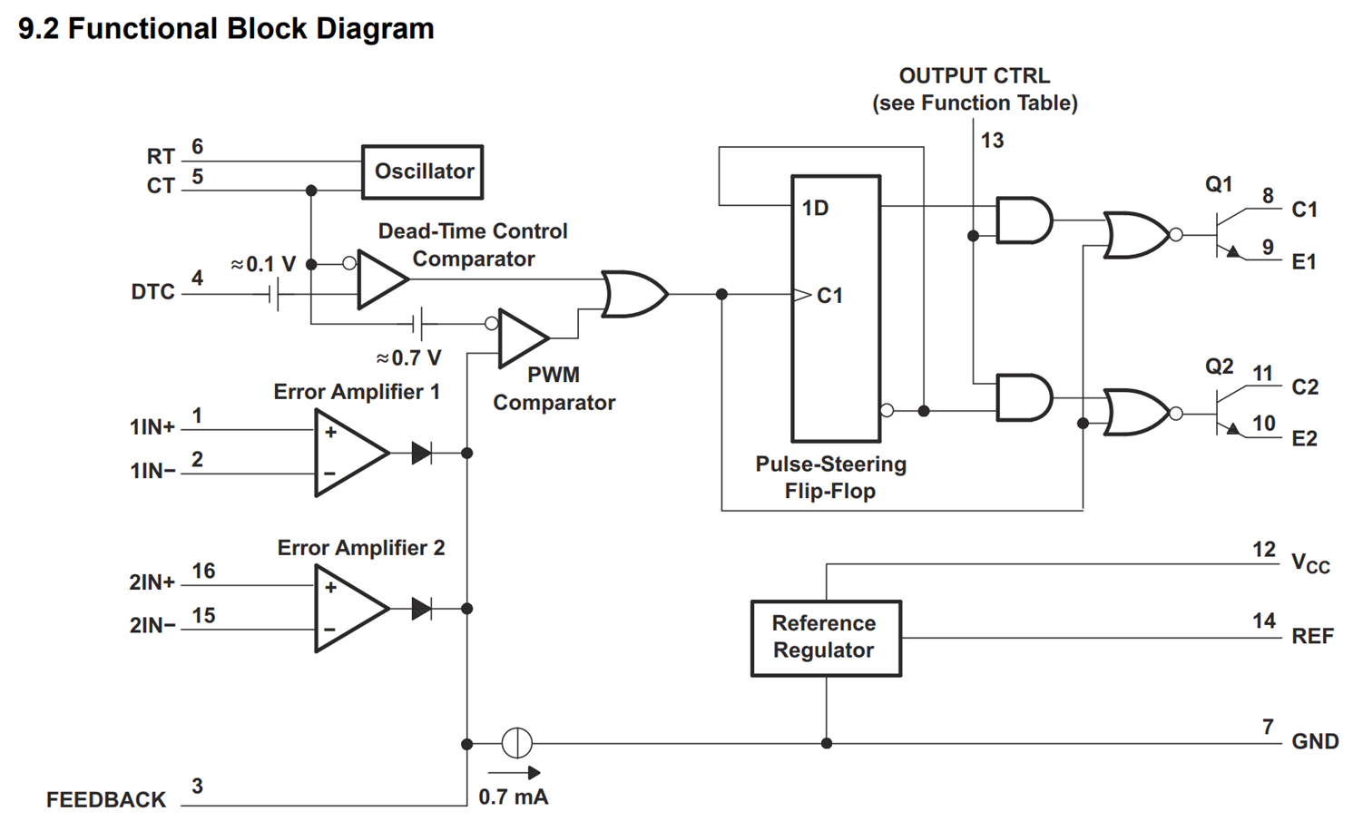
Looking around, I realized that a super-low-cost chip already contains the oscillator and comparator! It’s the TL494 , which is an ancient chip but still used in a lot of switching power supplies. Ordinarily, the TL494 generates PWM for driving transformer windings, and the control signals arrive at op-amp inputs on the chip. However, since we are only interested in simple PWM generation, it is possible to force the op-amp outputs low, putting them out of the equation, and instead feed an analog control voltage into a pin called Feedback, as can be seen in the block diagram.
image

 (image source: Texas Instruments website)

In the circuit below (which is pretty much just the test circuit from the datasheet), resistor R2 and the connections to pins 1,2,16, and 15 are used to permanently set the op amp outputs to low.

Components R1 and C1 are used to set the sawtooth oscillator frequency; it is about 12.5 kHz with the values shown. The TL494 requires at least 7V to operate, and there is an internal 5V regulator with an output on pin 14. It is used to provide the pull-up voltage using resistor R3, for the 5V PWM output. There is a spare output which isn’t being used (the CTRL pin is used to select the single-output mode).

image

That’s it! The above circuit costs about £0.70 even in a single quantity since the TL494 is so cheap. For isolation, adding an optocoupler to the output would add another 0.20 to the cost.

image

About the only main drawback* to the circuit is that the PWM duty cycle cannot quite reach zero percent. That’s because the TL494 isn’t intended as a fully general-purpose PWM output. It is intended for power supply applications. The PWM is inhibited from reaching 0% because of a small positive voltage that is added to the input of a pin called DTC (pin 4). There is a trick to forcing the chip to output PWM down to zero percent, but it isn’t straightforward; it needs a small negative voltage applied to pin 4 (this isn’t a documented method, but it seems to work with the TL494 that I tried). Anyway, it’s not always necessary to require 0% PWM for many other applications (for instance, hobby servo control doesn’t require zero percent; by replacing R1 with 47k and C1 with 100nF, the circuit above can be used as a servo tester), so I left the circuit as it is, with just the single supply.

*Actually, another drawback is that the chip requires at least 7V. It would be nice if it operated from 5V.

Testing It

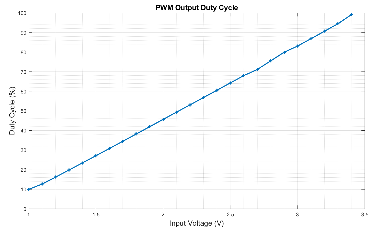
I applied known voltages at the input and measured the output duty cycle using a ‘scope. The results are in the chart below. It was fairly linear between 1V and 3.4V. From the chart, it is clear this is not an instrumentation-grade solution. Nevertheless, it could be suitable for far less demanding use cases, and as mentioned, it’s super-cheap and will provide isolation with a low-cost opto-isolator. I didn't use it in the end because the low-pass filtering has a slow response, at least tens of milliseconds for the PWM rate being used (although there are ways to reduce this). However, that would be perfectly suitable for many applications.
image

Thanks for reading!

  • Sign in to reply
  • michaelkellett
    michaelkellett over 2 years ago in reply to shabaz

    Some thoughts in the order they occurred:

    The linearity at low currents won't be brilliant, but for PSU monitoring this probably won't matter too much.

    The input looks odd - the optocoupler is biased to be uni-polar so GNDA should be common with the HV in connector pin 1, and R7 should be zero.

    You can make a bipolar optocoupler design by biasing the led ON.

    An OPA192 is overkill - OPA197 is similar (less good DC offset ) but cheaper and easier to get.

    Noise from the switcher may be an issue, some inductance in the filtering would help.

    Using a OPA2192 or OPA2197 would be cheaper - hand soldering MSOP packages is OK.

    I don't like dropping 1kV across a single SM resistor.

    I would build one (if you have a board).

    MK

    • Cancel
    • Vote Up 0 Vote Down
    • Sign in to reply
    • More
    • Cancel
  • shabaz
    shabaz over 2 years ago

    I was thinking of using a linear optocoupler, there is this figure 14B in the HCNR200 datasheet. 

    image

    Translated into this circuit, for up to 1kV measurement with about 1uA loading, and I hope with OK bandwidth:

    image

    It's large enough that it may be better to just build this on a PCB rather than other prototyping methods. It would be awesome if people could review it, and I'll lay it out on a PCB in the next few days once it has been scrutinized. Also, anyone interested to build it? It would be nice to debug together!

    Although the £1/$1 price is left in the rear-view : ( it is maybe £20-£25 of parts in single qty.

    Obviously not laid out like this, but just to see the approx soldering effort:

    image

    • Cancel
    • Vote Up 0 Vote Down
    • Sign in to reply
    • More
    • Cancel
  • DAB
    DAB over 2 years ago

    Very nice find.

    Now I have to go look in my stash to see if I have any of the chips.

    • Cancel
    • Vote Up 0 Vote Down
    • Sign in to reply
    • More
    • Cancel
  • shabaz
    shabaz over 2 years ago in reply to BigG

    Hi Colin,

    They were trying to amalgamate several things on that waveform diagram that would not ordinarily be seen together, so that makes it hard to follow. That DTC ramp on the left half of the diagram for instance, is just trying to show that if the DTC pin is increased in amplitude by any external circuit, then it makes the PWM output (on C1) increase its duty cycle. So, in the circuit that I used, the DTC pin was permanently set as low as possible (0V), to effectively stop using the DTC pin behaviour. The feedback pin is instead what got used (i.e. the right half of that diagram; it shows it as a ramp but that's actually the analog input in the circuit, it's not a ramp, it is just whatever the input voltage is).

    If you probe the capacitor (the CT pin), then the fixed ramp waveform is seen:

    image

    As you say, it will not change, it's fixed by the R1 and C1, and it's a ramp from 0V to 2.6V approx. Internally, the chip is comparing the combined input signals (in the case of the circuit above, it is just the Feedback pin since everything else is set to zero) with the ramp, and whenever the ramp output is lower (actually, whenever the ramp output plus 0.7V is lower [the 0.7V is some internal fixed offset]) than the feedback signal, then the PWM high period occurs. So, by varying the feedback voltage between about 0.7V and 3.3V, the PWM high period varies (i.e. duty cycle varies).

    • Cancel
    • Vote Up 0 Vote Down
    • Sign in to reply
    • More
    • Cancel
  • shabaz
    shabaz over 2 years ago in reply to michaelkellett

    Hi Michael,

    Nice retrofit board! That microcontroller solution is not expensive either, which is nice to see. 

    I was looking at a various existing designs using TL431, but they all had the majority of the feedback loop design on the secondary side, so that made me wonder if any designs had managed to use it in some other way, but I couldn't find an answer. However I too am planning to try an opto method next, using HNRC200 https://cpc.farnell.com/broadcom/hcnr200-300e/optocoupler-smd-analog/dp/SC17285?st=hcnr200 which I've never tried before, so that will be interesting. I've not decided which circuit to use yet; the datasheet has a lot of suggestions. I've polydoh'd it onto some pins ready for prototyping!

    Unfortunately, using this part would put it around the same cost (perhaps more expensive) than microcontroller+normal opto, so it's not looking attractive yet!

    image

    • Cancel
    • Vote Up 0 Vote Down
    • Sign in to reply
    • More
    • Cancel
<>
element14 Community

element14 is the first online community specifically for engineers. Connect with your peers and get expert answers to your questions.

  • Members
  • Learn
  • Technologies
  • Challenges & Projects
  • Products
  • Store
  • About Us
  • Feedback & Support
  • FAQs
  • Terms of Use
  • Privacy Policy
  • Legal and Copyright Notices
  • Sitemap
  • Cookies

An Avnet Company © 2026 Premier Farnell Limited. All Rights Reserved.

Premier Farnell Ltd, registered in England and Wales (no 00876412), registered office: Farnell House, Forge Lane, Leeds LS12 2NE.

Follow element14

  • X
  • Facebook
  • linkedin
  • YouTube