element14 Community
element14 Community
    Register Log In
  • Site
  • Search
  • Log In Register
  • Community Hub
    Community Hub
    • What's New on element14
    • Feedback and Support
    • Benefits of Membership
    • Personal Blogs
    • Members Area
    • Achievement Levels
  • Learn
    Learn
    • Ask an Expert
    • eBooks
    • element14 presents
    • Learning Center
    • Tech Spotlight
    • STEM Academy
    • Webinars, Training and Events
    • Learning Groups
  • Technologies
    Technologies
    • 3D Printing
    • FPGA
    • Industrial Automation
    • Internet of Things
    • Power & Energy
    • Sensors
    • Technology Groups
  • Challenges & Projects
    Challenges & Projects
    • Design Challenges
    • element14 presents Projects
    • Project14
    • Arduino Projects
    • Raspberry Pi Projects
    • Project Groups
  • Products
    Products
    • Arduino
    • Avnet & Tria Boards Community
    • Dev Tools
    • Manufacturers
    • Multicomp Pro
    • Product Groups
    • Raspberry Pi
    • RoadTests & Reviews
  • About Us
  • Store
    Store
    • Visit Your Store
    • Choose another store...
      • Europe
      •  Austria (German)
      •  Belgium (Dutch, French)
      •  Bulgaria (Bulgarian)
      •  Czech Republic (Czech)
      •  Denmark (Danish)
      •  Estonia (Estonian)
      •  Finland (Finnish)
      •  France (French)
      •  Germany (German)
      •  Hungary (Hungarian)
      •  Ireland
      •  Israel
      •  Italy (Italian)
      •  Latvia (Latvian)
      •  
      •  Lithuania (Lithuanian)
      •  Netherlands (Dutch)
      •  Norway (Norwegian)
      •  Poland (Polish)
      •  Portugal (Portuguese)
      •  Romania (Romanian)
      •  Russia (Russian)
      •  Slovakia (Slovak)
      •  Slovenia (Slovenian)
      •  Spain (Spanish)
      •  Sweden (Swedish)
      •  Switzerland(German, French)
      •  Turkey (Turkish)
      •  United Kingdom
      • Asia Pacific
      •  Australia
      •  China
      •  Hong Kong
      •  India
      •  Korea (Korean)
      •  Malaysia
      •  New Zealand
      •  Philippines
      •  Singapore
      •  Taiwan
      •  Thailand (Thai)
      • Americas
      •  Brazil (Portuguese)
      •  Canada
      •  Mexico (Spanish)
      •  United States
      Can't find the country/region you're looking for? Visit our export site or find a local distributor.
  • Translate
  • Profile
  • Settings
Open Source Hardware
  • Technologies
  • More
Open Source Hardware
Forum Archaeology Resistivity Meter
  • Blog
  • Forum
  • Documents
  • Events
  • Polls
  • Members
  • Mentions
  • Sub-Groups
  • Tags
  • More
  • Cancel
  • New
Join Open Source Hardware to participate - click to join for free!
Actions
  • Share
  • More
  • Cancel
Forum Thread Details
  • Replies 332 replies
  • Subscribers 321 subscribers
  • Views 44559 views
  • Users 0 members are here
  • armp
  • archaeology resistivity meter
Related

Archaeology Resistivity Meter

kltm
kltm over 5 years ago

Hi I'm looking for ideas on an update to a resistivity meter for archaeology. The only published designs for diy were in 2 magazines. One was published in 1997 and the other in 2003. I have copies of both articles available. The reason behind this is the current high cost of available equipment, usually well beyond the reach of most archaeological groups. I've attached a basic block diagram. In the first magazine article the meter is very basic. It relied on the operators to write down the reading given as the survey was taken. Given that a normal survey grid is 20m x 20m and 1 reading is taken on every sq mtr there would be 400 readings to write down and then input into a program used to interpret the results. The later article is really an update to the first where a PIC has been added to record the readings. This again is prone to error, because eadings are taken manually by pressing a button.

I'm sure given the advances in electronics there must be better ways. 


image

  • Sign in to reply
  • Cancel

Top Replies

  • kltm
    kltm over 5 years ago in reply to michaelkellett +8
    Hi Michael This all sounds very interesting and encouraging. I see you have found the original article, the update is also on slideshare somewhere. I haven’t really thought much about cost, but as you…
  • michaelkellett
    michaelkellett over 5 years ago in reply to shabaz +7
    I can't live with that - I have to have symmetry The problem is that the Howland current pump doesn't constrain the voltage on the load at all when perfectly balanced - and my LTSpice model is unrealistically…
  • michaelkellett
    michaelkellett over 5 years ago in reply to michaelkellett +7
    AS promised - now for the phase sensitive detector. I couldn't easily model this in LTSpice, which is no great surprise because it needs multiplication and square roots. I used Simulink in MATLAB - which…
  • fmilburn
    fmilburn over 5 years ago in reply to davemartin

    Hi Dave,


    I understand the need for assurance that the capability of older instruments and knowledge built on them is not lost.  Michael is doing a comparison of square wave with sinusoidal excitation.  And as Shabaz has pointed out the outlined design is quite capable of putting out a square wave and synching with it.  That should allow the value of a flexible design with additional capability to be assessed.


    Frank

    • Cancel
    • Vote Up +3 Vote Down
    • Sign in to reply
    • Cancel
  • michaelkellett
    michaelkellett over 5 years ago in reply to michaelkellett

    AS promised - now for the phase sensitive detector.

    I couldn't easily model this in LTSpice, which is no great surprise because it needs multiplication and square roots.

    I used Simulink in MATLAB - which is very much a paid for tool (although they do offer very good discounts to home users.)


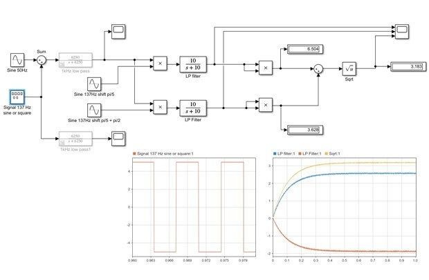
    The model is fairly self explanatory:

    image


    The left hand plot shows the input signal without interference added.

    The input low pass filter is disconnected.

    I've added some phase shift (pi/5 radians).

    The amplitude of the output is 3.183V


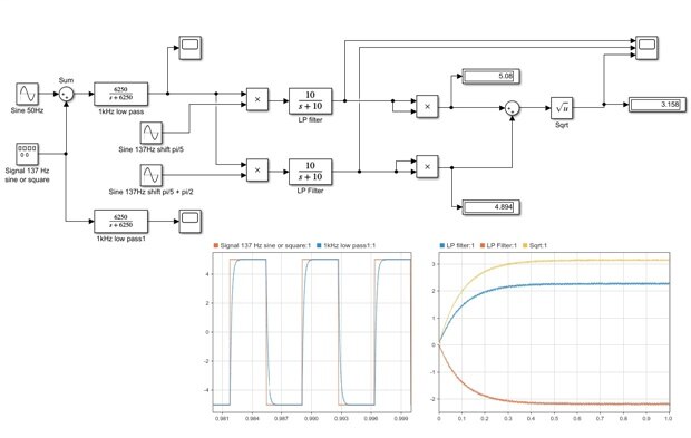
    image

    With the filter engaged you can see that its doesn't have a huge visual effect on the signal.

    The output voltage is 3.158 so the change is 0.0785%


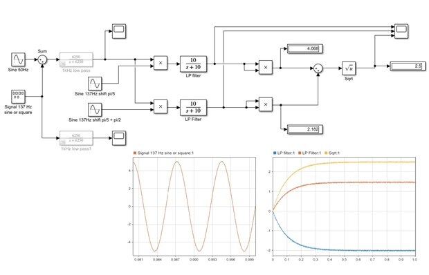
    image

    This is a sine wave input with no filter, the output is 2.500 V

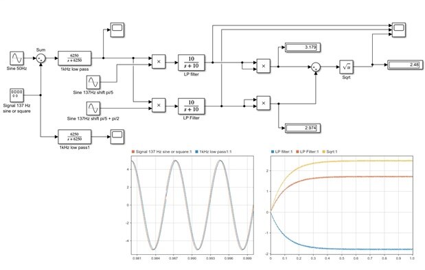
    image

    This is the sine wave input with the filter, you can see that it introduces a discernible phase change.

    The output is 2.48 V so the change is 0.08%.


    So we've demonstrated that the phase sensitive detector is not affected by changes in the system bandwidth

    (except where they affect the gain at the tuned frequency).

    And it makes no difference if the excitation is a sine wave or a square wave.


    (You may be wondering why the sine wave amplitude is 2.50V and the square wave 3.183V, that's because both

    are 5V pk but the first harmonic in a square wave has an amplitude of 4/pi  * pk = 1.273,

    and 2.500 * 1.273 = 3.183


    But we saw in the previous series of simulations of the simple synchronous detector that the introduction of

    the 1kHz filter cause a 10% error in the reading.


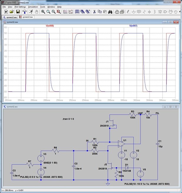
    In the filtered square wave simulation in this post you can compare the square wave with its filtered version.

    I've added a bit the the LTSpice model of the simple synchronous detector so you can do the same thing.


    image


    I'm hoping that by now I've convinced you that the phase sensitive detector really does work a great deal better

    being much less susceptible to out of band interference or response changes.


    To put it another way the simple detector is sensitive to the impedance of the earth up to at least 10x the nominal frequency.


    Since the PSD only detects the fundamental frequency of the excitation it is obviously a waste of power to transmit the harmonics

    it will ignore.


    So sine wave excitation and a PSD detector, all other things being equal, is less susceptible to interference, less susceptible

    to out of band changes in earth impedance and uses less power.


    What's not to like image


    MK

    • Cancel
    • Vote Up +7 Vote Down
    • Sign in to reply
    • Cancel
  • phoenixcomm
    phoenixcomm over 5 years ago in reply to michaelkellett

    michaelkellett  Michael, way cool, over my head as I don't do analog stuff, that is except with tubes for my stereo.

    ~~Cris

    • Cancel
    • Vote Up 0 Vote Down
    • Sign in to reply
    • Cancel
  • michaelkellett
    michaelkellett over 5 years ago in reply to phoenixcomm

    If you are into HiFi you will have phase sensitive detectors in your ears !


    Mine used to be quite good but are less so now.


    MK

    • Cancel
    • Vote Up +1 Vote Down
    • Sign in to reply
    • Cancel
  • phoenixcomm
    phoenixcomm over 5 years ago in reply to michaelkellett

    michaelkellett Yes!image

    • Cancel
    • Vote Up +1 Vote Down
    • Sign in to reply
    • Cancel
  • davemartin
    davemartin over 5 years ago in reply to michaelkellett

    Thanks Michael, Shabaz and Frank.


    With absolutely no disrespect to the collective expertise, and probably an indication of my lack of understanding of some of the posts, it still feels to me like this is aimed at measuring the resistance or impedance of a 'device under test', and I'm still a little uncomfortable that proposals may not match the actual requirement, so if I may I'll just recap.


    Archaeological 'resistance' or 'resistivity' measurements are taken with fundamentally a four-probe setup. This is to reduce the effect of contact resistance (which can be up to maybe 40k and vary significantly between successive sample points) and the 'signal' which can vary by perhaps only single-digit of ohms or fractions of an ohm.


    To achieve this, there are effectively two completely electrically independent circuits. One, which injects a constant-current between two probes or electrodes (C1 and C2) which may well be >50 metres apart (in some instruments it is a constant voltage rather than constant current injected). There is then a high-input-impedance voltage measurement between probes P1 and P2.


    In a typical twin-probe archaeological survey, P1 and C1 are located in a fixed location (at least for the duration of a grid) and mobile probes (P2 and C2) affixed to a frame are traversed by the operator to take readings at known points within a grid. The spacing between the probes P2 and C2 on the frame is chosen with an eye to the likely depth of feature expected on the site; the fixed probes P1 and C1 should be at a similar distance apart. As current flows through approximately a hemisphere with C1 and C2 points on the circumference, to avoid distortion due to the changing volume beneath the measurements, it is normal that the fixed probes P1C1 are at least 30x the probe separation distant from the grid edge.


    The constant DC current is injected via a single wire core from the source in the instrument to remote injection C1, then flows via the earth (in bulk, not a skin effect) back to mobile C2 and then back to the source in the instrument box. The voltage gradient around the C probes is influenced by the underlying geology and man-made pertubation, and these changes in voltage measured at successive points (between fixed P1 and mobile P2 on the frame, via a second wire core) are what are plotted and can in due course hint at what lays beneath the soil.


    The only connection necessary between the current injection 'C' circuitry and the voltage measuring 'P' circuitry is that in some instruments the start of measurements is held-off by a pre-programmed delay from the edge of the current pulse. The DC constant current is reversed periodically to avoid polarising the material around the C probes.


    Readings start when the mobile probes complete the circuit, but care is needed as electrical contact can be made with, say, grass as the frame probes are plunged into the earth, therefore successive readings are taken, across multiple reversals, until they are sufficiently settled.


    Dave

    • Cancel
    • Vote Up +2 Vote Down
    • Sign in to reply
    • Cancel
  • michaelkellett
    michaelkellett over 5 years ago in reply to davemartin

    Well Dave, the whole point of this open source design malarky is to talk about stuff.


    There is nothing unusual or special about 4 wire measurements - any decent DMM does them.

    Our plan has addressed that from the start.


    Beck's design does not work accoridng to the general scheme you describe, we know that for sure because the ciruit is in the public domain.

    The Geoscan RM85 uses a phase sensitive detector.


    As far as I can tell all the instruments available use AC excitation, primarily to avoid electrolysis effects. A soon as you use AC

    the system is susceptible to AC interference so you need, in some way or other, a bandpass filter to allow only the excitation

    frequency to be measured.


    There are many ways this can be achieved, but two that are common are the synchronous detector (like Beck), which is fairly easy

    to implement entirely in hardware, and a sin/cos type of phase sensitive detector which is extemely difficult to implement

    in hardware but presents no problems to a hybrid design.


    The 'delay from an edge to a single sample' method that you describe offers no discrimination against interference at all. This is

    clearly shown in the second plot of my anaysis of the Beck design. If you were to average many readings taken in this way

    it would behave like a bad implementation of the classical synchronous detector but would be even more susceptible to out of band

    noise.


    However, the proposed design is flexible, so it could be programmed to operate as you suggest. If we should get to the stage of

    testing prototypes we could try it.


    In passing I should point out that neither the synchronous detector nor the phase sesnitive detector offer any suppresion of interference

    over a single cycle. They both rely on frequency shifting the inteference and using a low pass filter to remove it. The band width of the

    detector is inversely proportional  to the cut off frequency of the low pass filter, the response time of the detector is inversely proprtional to

    the band width.


    It is common with PSDs to average over a fixed number of cycles, there is a Schlumberger paper with some nice graphs of

    selectivity compared with number of samples averaged. Sorry I don't have a link to hand.


    A filter implemented in software can easily change gear, using a fast response and wider bandwidth to detect ground contact and

    then using a narrower bandwidth to take readings at the maximum accuracy.


    One of the many advantages of the sine wave excited PSD technique is that all the signal power is used, both in transmission and

    recpetion and that each reading represents the averageing together of hundreds or thousands of ADC samples thus allowing

    a very large dynamic range and low noise.


    MK

    • Cancel
    • Vote Up +2 Vote Down
    • Sign in to reply
    • Cancel
  • robbarter
    robbarter over 5 years ago

    Just came across this thread and it brought back happy memories of about 10 years ago when I did a resistivity survey near a Roman bath in East Sussex.  I too thought about building my own design but work and life got in the way.


    The location aspect was the main thing that hit me as I was walking up and down the lines as has been mentioned ealier in the thread.   Both GPS accuracy, update rate and the point when the frame is vertical have been touched upon.   You can now buy cheap GPS modules for £4.50 from AliExpress (e.g. Quectel L96) which, according to the spec sheet, can update at 10Hz.   Assuming a walking rate with frame in hand of about 1m/sec (2.4mph) that would give a relative accuracy of 10cm, the reading being taken when an accelerometer chip indicates the frame is vertical.  GPS of course in low cost modules is only accurate to a few meters but if a 2nd GPS receiver were placed at a fixed known location in the field and able to communicate back to the mobile unit would that give you a more accurate differential reading?


    Auto transfer at the end of a grid of the accumulated readings to a laptop would was another feature that sprang to mind those many years ago.  Meaning the minions can carry on trudging backwards and forwards while the boss looks at the results.

    • Cancel
    • Vote Up +3 Vote Down
    • Sign in to reply
    • Cancel
  • shabaz
    shabaz over 5 years ago in reply to michaelkellett

    It will be exciting to see the performance - can't wait : )

    The digital nature is opening up lots of possibilities to experiment and get the most out of any measurements. Hopefully it directly results in clarified imaging : )

    Another nice thing is that correlated double sampling (CDS) could be used (if it was found necessary) where as well as the two quadrature signals, 180 degree out-of phase to both of them could be sampled too, and then subtracted (i.e. if there are any offsets anywhere pre-digital then they get removed too!).

    I'm already thinking how the design could be later adapted/re-spinned to handle dual simultaneous ADCs off the FPGA, for different sensors that may not require dual sources. There was a very primitive magnetic gradiometer here (about halfway down: Portable Multi-Channel Recorder - Review  ), it has two 0-5V outputs.

    Anyway that's major feature creep and very untested.. I only experimented with it briefly.

    • Cancel
    • Vote Up +4 Vote Down
    • Sign in to reply
    • Cancel
  • shabaz
    shabaz over 5 years ago in reply to robbarter

    Hi Rob,


    The auto-transfer should be easy to do,  it's possible (I don't mind attempting it) to write a mobile app, so you can plug in the unit to the phone (it has a USB connector) and upload the data and e-mail it - the application could even attach a mobile-phone-determined GPS co-ordinate or a google maps link of where you're standing when you e-mail it for example.


    GPS positioning accuracy using two modules will still be inaccurate to solve this way though. I'll carry on thinking, but all the location methods I've currently thought of which are high-accuracy, are either high-cost or reduced practicality to use in the field, or are major standalone projects in their own right, and most are all three : (

    • Cancel
    • Vote Up +2 Vote Down
    • Sign in to reply
    • Cancel
<>
element14 Community

element14 is the first online community specifically for engineers. Connect with your peers and get expert answers to your questions.

  • Members
  • Learn
  • Technologies
  • Challenges & Projects
  • Products
  • Store
  • About Us
  • Feedback & Support
  • FAQs
  • Terms of Use
  • Privacy Policy
  • Legal and Copyright Notices
  • Sitemap
  • Cookies

An Avnet Company © 2025 Premier Farnell Limited. All Rights Reserved.

Premier Farnell Ltd, registered in England and Wales (no 00876412), registered office: Farnell House, Forge Lane, Leeds LS12 2NE.

ICP 备案号 10220084.

Follow element14

  • X
  • Facebook
  • linkedin
  • YouTube