element14 Community
element14 Community
    Register Log In
  • Site
  • Search
  • Log In Register
  • About Us
  • Community Hub
    Community Hub
    • What's New on element14
    • Feedback and Support
    • Benefits of Membership
    • Personal Blogs
    • Members Area
    • Achievement Levels
  • Learn
    Learn
    • Ask an Expert
    • eBooks
    • element14 presents
    • Learning Center
    • Tech Spotlight
    • STEM Academy
    • Webinars, Training and Events
    • Learning Groups
  • Technologies
    Technologies
    • 3D Printing
    • FPGA
    • Industrial Automation
    • Internet of Things
    • Power & Energy
    • Sensors
    • Technology Groups
  • Challenges & Projects
    Challenges & Projects
    • Design Challenges
    • element14 presents Projects
    • Project14
    • Arduino Projects
    • Raspberry Pi Projects
    • Project Groups
  • Products
    Products
    • Arduino
    • Avnet Boards Community
    • Dev Tools
    • Manufacturers
    • Multicomp Pro
    • Product Groups
    • Raspberry Pi
    • RoadTests & Reviews
  • Store
    Store
    • Visit Your Store
    • Choose another store...
      • Europe
      •  Austria (German)
      •  Belgium (Dutch, French)
      •  Bulgaria (Bulgarian)
      •  Czech Republic (Czech)
      •  Denmark (Danish)
      •  Estonia (Estonian)
      •  Finland (Finnish)
      •  France (French)
      •  Germany (German)
      •  Hungary (Hungarian)
      •  Ireland
      •  Israel
      •  Italy (Italian)
      •  Latvia (Latvian)
      •  
      •  Lithuania (Lithuanian)
      •  Netherlands (Dutch)
      •  Norway (Norwegian)
      •  Poland (Polish)
      •  Portugal (Portuguese)
      •  Romania (Romanian)
      •  Russia (Russian)
      •  Slovakia (Slovak)
      •  Slovenia (Slovenian)
      •  Spain (Spanish)
      •  Sweden (Swedish)
      •  Switzerland(German, French)
      •  Turkey (Turkish)
      •  United Kingdom
      • Asia Pacific
      •  Australia
      •  China
      •  Hong Kong
      •  India
      •  Korea (Korean)
      •  Malaysia
      •  New Zealand
      •  Philippines
      •  Singapore
      •  Taiwan
      •  Thailand (Thai)
      • Americas
      •  Brazil (Portuguese)
      •  Canada
      •  Mexico (Spanish)
      •  United States
      Can't find the country/region you're looking for? Visit our export site or find a local distributor.
  • Translate
  • Profile
  • Settings
Open Source Hardware
  • Technologies
  • More
Open Source Hardware
Forum LiPo 3.3V Linear Regulation - Chip Suggestions?
  • Blog
  • Forum
  • Documents
  • Events
  • Polls
  • Members
  • Mentions
  • Sub-Groups
  • Tags
  • More
  • Cancel
  • New
Join Open Source Hardware to participate - click to join for free!
Actions
  • Share
  • More
  • Cancel
Forum Thread Details
  • State Verified Answer
  • Replies 12 replies
  • Subscribers 313 subscribers
  • Views 2649 views
  • Users 0 members are here
Related

LiPo 3.3V Linear Regulation - Chip Suggestions?

jgreenb8@gmail.com
jgreenb8@gmail.com over 9 years ago

Greetings,


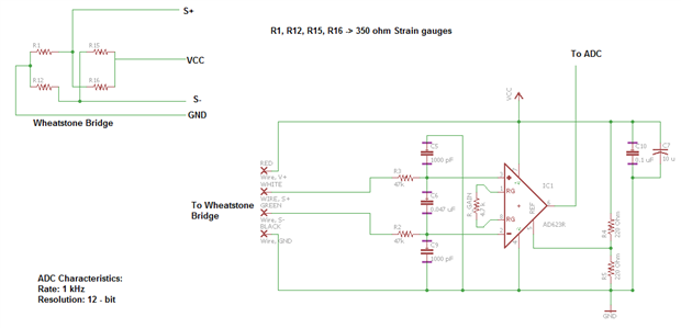
I'm working with a design I developed and I'm running into the shortcomings of Inductor based regulators. I'm trying to regulate a 3.7V nom. lipo battery to 3.3V for ADC sampling of a strain gauge bridge. Unfortunately I am running into issues with noise and I believe it's due to the oscillations of the voltage regulator I am currently using, the TI TPS61200.


Does anyone know of a good linear voltage regulator that can take the 3.7-4.2 V of a LiPo and still hold a 3.3V stable output? 


I've searched for some time and I am not having much luck. Perhaps I am thinking of this from the wrong approach.


Many Thanks!

  • Sign in to reply
  • Cancel
  • dmaruska
    0 dmaruska over 9 years ago

    What is your excitation voltage and what is your current draw? Do you have a schematic to share?


    Regards,


    Dave M.

    • Cancel
    • Vote Up 0 Vote Down
    • Sign in to reply
    • Verify Answer
    • Cancel
  • clem57
    0 clem57 over 9 years ago

    Jacob Greenburg,

         https://www.circuitsathome.com/dc-dc/designing-dc-dc-converters-using-ti-tps61200-controller  is a good read. But I see the current starts at 1500 mA and ends just at ~800 mA at discharge of LiPo which should NOT go below 2.7V. I hope you did not go below and reverse the polarity on the LiPo. Since the current is variable when the voltage held at 3.3 V you should expect the current to drop. If noise is the problem look at http://www.ti.com/product/tps62230 . In the description you can force PWM mode that will lower noise . But this can handle only 500 mA!image


    Clem

    • Cancel
    • Vote Up 0 Vote Down
    • Sign in to reply
    • Verify Answer
    • Cancel
  • jgreenb8@gmail.com
    0 jgreenb8@gmail.com over 9 years ago in reply to dmaruska

    By excitation voltage I believe you mean the battery right? in that case it would be the 3.4V to 4.2V of the LiPo battery.


    I'm not entirely certain of my current draw, but I believe it to be around 360mA. The primary sources of this is the following:

    XBee Wifi Module S6b, peak current of 310 mA

    Teensy Proto Board, Peak Current 35 mA

    Resistor Bridge, 10 mA

    Amplifier, Negligible ~25 microA

    Status LED's have some too, but I removed those from the design.


    The circuit is designed to run from a nominal 3.3V for the whole system. I've included a schematic of the ADC portion that I believe is amplifying all variations from the power supply.


    image

    • Cancel
    • Vote Up 0 Vote Down
    • Sign in to reply
    • Verify Answer
    • Cancel
  • dmaruska
    0 dmaruska over 9 years ago in reply to jgreenb8@gmail.com

    I was reading over the datasheet for the operation modes and noticed this compared to your schematic on the REF line. and Yes the Excitation was the bridge supply.


    image


    image

    • Cancel
    • Vote Up 0 Vote Down
    • Sign in to reply
    • Verify Answer
    • Cancel
  • jgreenb8@gmail.com
    0 jgreenb8@gmail.com over 9 years ago in reply to dmaruska

    The issue I have had with this is that I have negative swing on my wheatstone bridge that would drive the voltage into the ground rail and even negative. To accommodate for that I put the ref voltage in the middle at 1.65V with the voltage divider. I then use this reading as a zero off the ADC and calibrate my bridge for whichever direction the sensor would see.


    Could the noise be from the ref pin? As you can see I have heavily filtered the input the the amp but I have just a straight, unfiltered resistor divider for it.


    "EDIT"

    I just noticed the other image on your reply. This is more or less how I have the system setup with the exception being the ref pin as you mentioned. Actually the other exception is that I use the on board ADC of the microprocessor, not an independent one. I'm considering the advantages of having an independent ADC for improving my data rates and letting the processor do transmits over Wifi, but that might be a topic of another time.

    • Cancel
    • Vote Up 0 Vote Down
    • Sign in to reply
    • Verify Answer
    • Cancel
  • dmaruska
    0 dmaruska over 9 years ago in reply to jgreenb8@gmail.com

    From a trouble shooting point of view, can you run this from a bench power supply that you can select the voltage that you want.  With a bench power supply you can use it to remove that portion of the equation, and focus on the bridge and amp, then when you are sure its working they way you expect, switch back to the battery.  Also if you are bread boarding this, the bread board (The type and you can just plug into) adds capacitance to the circuit.  Break it in to small segments.  You can use a bench power supply to drive the Amp input and reference the grounds on the battery circuit and the bench supply and verify its operation.  Once you are sure each part works correctly, add on the next portion and retest.  Any RF powered items from the same power source you will want to insure RF is not being fed back through the power line.  If RF in not part of the circuit yet, be sure to look for it in the future when you add it.  You maybe surprised where the noise is coming from.


    Regards,


    Dave M.

    • Cancel
    • Vote Up 0 Vote Down
    • Sign in to reply
    • Verify Answer
    • Cancel
  • mlease
    0 mlease over 9 years ago

    Jacob, I'm curious if you are seeing noise on a scope or are your ADC readings jumping around more than expected? If you are seeing it on the scope, at what point is the noise - on the Vcc line, on the bridge signals or on the output of the amplifier? If it is noise on Vcc, is it switching spikes or ripple or just an unsteady voltage?


    Assuming it is noise on Vcc and you've tried increasing the inductor value and adding more bulk capacitance, I would try (1) adding an LC filter on the output of the TPS61200 (2) inserting a small resistor between Vcc and your analog circuit and change the 0.1uF cap value as needed to filter the noise and (3) use a small LDO just for the analog circuit. Those may not be easy to do depending on the board layout so I would start with the easiest to do.


    Good luck!


    Mike

    • Cancel
    • Vote Up 0 Vote Down
    • Sign in to reply
    • Verify Answer
    • Cancel
  • jgreenb8@gmail.com
    0 jgreenb8@gmail.com over 9 years ago in reply to dmaruska

    dmaruska wrote:

    From a trouble shooting point of view, can you run this from a bench power supply that you can select the voltage that you want. 


    This is what first alerted me to the issue. I've been assembling the latest version of the prototypes that incorporated a PCB design instead of soldered perf board connections. The noise cleaned up significantly by going to a designated circuit as I expected, but as I assembled each system on the PCB I tested them independently. When I did this I was elated when I had next to no noise, of the order of roughly +/-1mV, however, when I connected the battery power circuit that noise jumped to +/- 5mV. (+/- 1mV even without shielded signal wire!) In the past I chased this problem by examining the power supply output on the scope and found it had ripple, but given the uncertainty with solder perf board I accepted this as the best accuracy I could easily obtain. With the PCB I got greedy and wanted a the cleaner signal that I was getting with the bench supply.

    • Cancel
    • Vote Up 0 Vote Down
    • Sign in to reply
    • Verify Answer
    • Cancel
  • jgreenb8@gmail.com
    0 jgreenb8@gmail.com over 9 years ago in reply to mlease

    Mike Lease wrote:


    Jacob, I'm curious if you are seeing noise on a scope or are your ADC readings jumping around more than expected? If you are seeing it on the scope, at what point is the noise - on the Vcc line, on the bridge signals or on the output of the amplifier? If it is noise on Vcc, is it switching spikes or ripple or just an unsteady voltage?


    See my previous reply to dmaruska, when I populated my PCB I checked each subsystem independently. The issue with the noise has been isolated to when I powered the circuit through the battery regulator, however, I did not check just the VCC line in circuit. My readings were on the output of the amplifier, I'll have to go and recheck Vcc on my scope. Perhaps I can compare Vcc and Vout at the same time. I'll try to post a screencap of my findings.


    Mike Lease wrote:


    Assuming it is noise on Vcc and you've tried increasing the inductor value and adding more bulk capacitance, I would try (1) adding an LC filter on the output of the TPS61200 (2) inserting a small resistor between Vcc and your analog circuit and change the 0.1uF cap value as needed to filter the noise and (3) use a small LDO just for the analog circuit. Those may not be easy to do depending on the board layout so I would start with the easiest to do.

    I see what you are saying here, Just filter out any variations from the power supply with a low pass filter. My experience with these is just an RC filter, I'll have to look up more regarding LC design. Are there any drawbacks from filtering the Vcc line? Why wouldn't this be inherent to the chip design if not?


    My room for options is limited but I might be able to find space, I am using a breakout board for the TPS61200 due to my ability to solder that size package. I'll have to use a small perf board to begin with and see if I can incorporate that with my next PCB layout.


    In regards to item 3, This may be a part of the main purpose of the post. I'm having a tough time finding an inductorless LDO that doesn't have a dropout voltage of > 400 mV.


    Thank you,

    Jacob

    • Cancel
    • Vote Up 0 Vote Down
    • Sign in to reply
    • Verify Answer
    • Cancel
  • mlease
    0 mlease over 9 years ago in reply to jgreenb8@gmail.com

    Jacob, which regulator are you using? Your original post said a TPS61200 but that is a boost regulator. If your regulator has a pulse skipping mode to improve light load efficiency you should disable that if you can. It will improve efficiency but at the expense of higher ripple.


    For an LC filter design I've used a program called Elsie that you can download from Elsie - electrical filter design program from Tonne Software, you should be able to use the free version for what you need to do. The noise from modern DC-DC regulators is low enough for digital circuits and many analog circuits so the additional parts usually aren't required. If you just filter the power to the analog circuit you should be able to get by with physically small inductor and cap.


    As far as LDOs go, take a look at the TI LP2980 for just powering your analog circuit. The dropout should be below 100mV if that circuit draw is 10mA as indicated earlier.


    One more thing to consider would be to use an RC filter on the amplifier output but put it right at the input to your micro. That assumes the frequency of the noise is much higher than the strain gauge transitions.


    Mike

    • Cancel
    • Vote Up 0 Vote Down
    • Sign in to reply
    • Reject Answer
    • Cancel
>
element14 Community

element14 is the first online community specifically for engineers. Connect with your peers and get expert answers to your questions.

  • Members
  • Learn
  • Technologies
  • Challenges & Projects
  • Products
  • Store
  • About Us
  • Feedback & Support
  • FAQs
  • Terms of Use
  • Privacy Policy
  • Legal and Copyright Notices
  • Sitemap
  • Cookies

An Avnet Company © 2025 Premier Farnell Limited. All Rights Reserved.

Premier Farnell Ltd, registered in England and Wales (no 00876412), registered office: Farnell House, Forge Lane, Leeds LS12 2NE.

ICP 备案号 10220084.

Follow element14

  • X
  • Facebook
  • linkedin
  • YouTube