element14 Community
element14 Community
    Register Log In
  • Site
  • Search
  • Log In Register
  • About Us
  • Community Hub
    Community Hub
    • What's New on element14
    • Feedback and Support
    • Benefits of Membership
    • Personal Blogs
    • Members Area
    • Achievement Levels
  • Learn
    Learn
    • Ask an Expert
    • eBooks
    • element14 presents
    • Learning Center
    • Tech Spotlight
    • STEM Academy
    • Webinars, Training and Events
    • Learning Groups
  • Technologies
    Technologies
    • 3D Printing
    • FPGA
    • Industrial Automation
    • Internet of Things
    • Power & Energy
    • Sensors
    • Technology Groups
  • Challenges & Projects
    Challenges & Projects
    • Design Challenges
    • element14 presents Projects
    • Project14
    • Arduino Projects
    • Raspberry Pi Projects
    • Project Groups
  • Products
    Products
    • Arduino
    • Avnet Boards Community
    • Dev Tools
    • Manufacturers
    • Multicomp Pro
    • Product Groups
    • Raspberry Pi
    • RoadTests & Reviews
  • Store
    Store
    • Visit Your Store
    • Choose another store...
      • Europe
      •  Austria (German)
      •  Belgium (Dutch, French)
      •  Bulgaria (Bulgarian)
      •  Czech Republic (Czech)
      •  Denmark (Danish)
      •  Estonia (Estonian)
      •  Finland (Finnish)
      •  France (French)
      •  Germany (German)
      •  Hungary (Hungarian)
      •  Ireland
      •  Israel
      •  Italy (Italian)
      •  Latvia (Latvian)
      •  
      •  Lithuania (Lithuanian)
      •  Netherlands (Dutch)
      •  Norway (Norwegian)
      •  Poland (Polish)
      •  Portugal (Portuguese)
      •  Romania (Romanian)
      •  Russia (Russian)
      •  Slovakia (Slovak)
      •  Slovenia (Slovenian)
      •  Spain (Spanish)
      •  Sweden (Swedish)
      •  Switzerland(German, French)
      •  Turkey (Turkish)
      •  United Kingdom
      • Asia Pacific
      •  Australia
      •  China
      •  Hong Kong
      •  India
      •  Korea (Korean)
      •  Malaysia
      •  New Zealand
      •  Philippines
      •  Singapore
      •  Taiwan
      •  Thailand (Thai)
      • Americas
      •  Brazil (Portuguese)
      •  Canada
      •  Mexico (Spanish)
      •  United States
      Can't find the country/region you're looking for? Visit our export site or find a local distributor.
  • Translate
  • Profile
  • Settings
Passive Components
  • Technologies
  • More
Passive Components
Forum Any one know what this is?
  • Blog
  • Forum
  • Documents
  • Quiz
  • Events
  • Polls
  • Members
  • Mentions
  • Sub-Groups
  • Tags
  • More
  • Cancel
  • New
Join Passive Components to participate - click to join for free!
Actions
  • Share
  • More
  • Cancel
Forum Thread Details
  • State Verified Answer
  • Replies 13 replies
  • Answers 6 answers
  • Subscribers 108 subscribers
  • Views 2959 views
  • Users 0 members are here
Related

Any one know what this is?

jw0752
jw0752 over 8 years ago

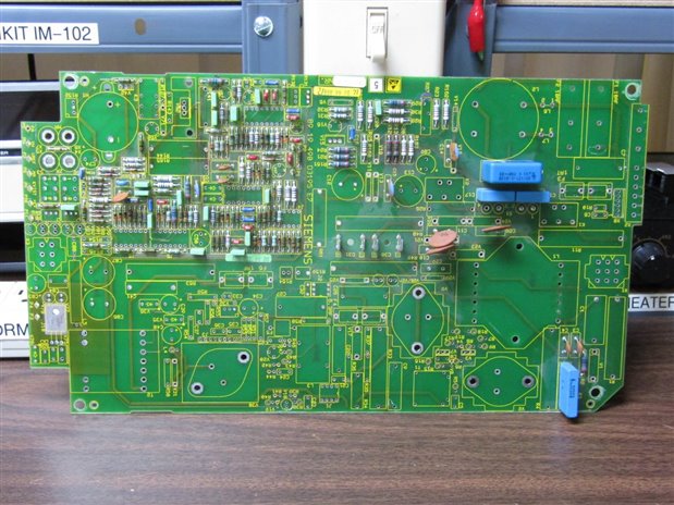
Disassembling a nice Siemens Circuit board from an X-Ray machine with a early 1990s manufacturer date. Among the salvaged parts was this little fellow:


image


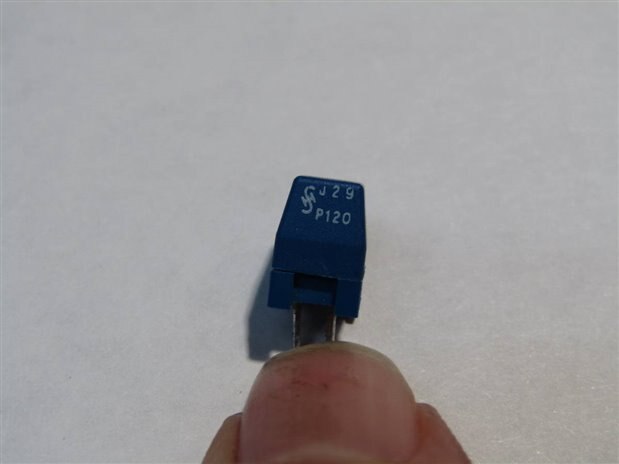
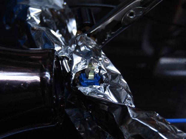
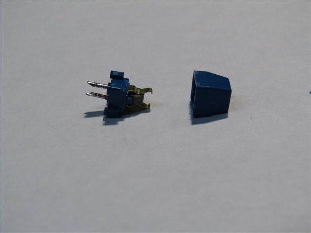
The blue case had the numbers J29 P120 and Siemens symbol. It looked like the case could be opened so I inserted a knife blade and opened it. Here is what it looked like inside. I set the insides up on the cover in the second shot to get a better picture.


image


image


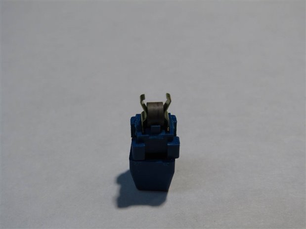
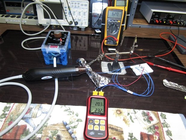
The device has 6.4K Ohms of resistance.


This is just my curiosity asking. Since the machine has European Design and other components I thought someone from there might recognize it.


Thanks

John


  • Sign in to reply
  • Cancel

Top Replies

  • shabaz
    shabaz over 8 years ago +4 verified
    Hi John, Interesting find! I've never seen such a device, but I did see a similar thing on ebay: PTC MINI MIVAR SIEMENS J29 P190 2PIN PEZZI 5 | eBay Apparently a 'switching thermistor' which as it gets…
  • jw0752
    jw0752 over 8 years ago in reply to shabaz +4 suggested
    Hi Shabaz, That was fast. Tomorrow I will run some temperature vs resistance tests on it to see how it reacts. Nice to see the exact thing listed on ebay. Either there is still some relevant application…
  • jc2048
    jc2048 over 8 years ago +4 suggested
    The passive section of Siemens became EPCOS and that then became a part of TDK. Here's a datasheet from their website https://en.tdk.eu/inf/55/db/PTC/PTC_Switching_Plastic_case_230V.pdf
Parents
  • jw0752
    0 jw0752 over 8 years ago

    Tonight I had the chance to run a crude experiment to see for myself what are the Temperature vs Resistance characteristics of this PTC. I used the following test set up.


    image


    The blue box is the control for the heat gun. I can produce temperatures between room temperature and 340 C. The Fluke is monitoring the resistance of the PTC device and the Red meter is a thermal couple thermometer of which I only used the bottom probe. The PTC is clipped to the Thermal Couple so that they have nearly the same temperature. The aluminum foil to to protect my plastic probe clips from melting. Here is a close up of the PTC and the Thermal Couple poking through the foil.


    image


    Here are the readings that I got from my test of this PTC:


    Temperature                         Resistance

    Degrees C                              Ohms

    ----------------                         ---------------

    20                                        6.8 K

    25                                        6.6 K

    30                                        6.2 K

    35                                        5.9 K

    45                                        5.5 K

    55                                        4.9 K

    65                                        4.5 K

    75                                        4.5 K

    85                                        5.4 K

    95                                      10.7 K

    105                                    36.5 K

    115                                      1.9 M

    125                                    13.0 M

    135                                    50.0 M


    I graphed this but I had to shift the resistance scale logarithmically  and it was too much of a mess to post but you can get the idea. While my measurements did not match the data sheet exactly it is probably due to my not matching the current of the manufacturers test conditions. The resistance of the PTC acts like a NTC thermistor from the 20 C room temperature to about 60 C and then it turns PTC and increases rapidly to 50 Megohms at 135 C. Thanks again to everyone who took the to put me on the right track to identifying this part.


    John

    • Cancel
    • Vote Up +4 Vote Down
    • Sign in to reply
    • Verify Answer
    • Reject Answer
    • Cancel
  • jc2048
    0 jc2048 over 8 years ago in reply to jw0752

    An easy way to do log graphs is to paste the data into a spreadsheet and get the software to do it for you. I put your values into the LibreOffice spreadsheet and got this


    image


    The shape is similar to the datasheet but, as you say, your curve going up is happening about 30C lower than theirs.

    • Cancel
    • Vote Up +3 Vote Down
    • Sign in to reply
    • Verify Answer
    • Reject Answer
    • Cancel
  • jw0752
    0 jw0752 over 8 years ago in reply to jc2048

    Hi Jon,


    Thanks for the suggestion on the graphing. I will take the time to learn how to do this for future graphs. Your analysis is right on the mark as to seeing the curve shifted to a lower temperature. I attributed this to my meter's current compared to the manufacturer's actual test setup. Another possibility though are the changes that may have occurred in the material over the last 27 years of use.


    John

    • Cancel
    • Vote Up +3 Vote Down
    • Sign in to reply
    • Verify Answer
    • Cancel
  • DAB
    0 DAB over 8 years ago in reply to jw0752

    Hi John,


    I think the trend is correct.


    The device was probably used to prevent overexposure.


    I think you will find that as the device runs, the temperature increases rapidly.  This simple device would detect the temperature change and throttle the current running to the x-ray projector so the patient would not be injured.


    DAB

    • Cancel
    • Vote Up +2 Vote Down
    • Sign in to reply
    • Verify Answer
    • Reject Answer
    • Cancel
  • jc2048
    0 jc2048 over 8 years ago in reply to jw0752

    I attributed this to my meter's current compared to the manufacturer's actual test setup.

    The datasheet suggests 4 seconds to take it to the switching point with the self-heating from a current of 20mA.


    But your meter current wouldn't be anything like that high - with a 9V battery, the highest possible current through 7k would be 1.3mA (Ohm's law), though in practice it would be much less. My handheld meter has a few 10s of uA for those kinds of resistances, though it may not work the same as your Fluke.


    You could try measuring just the change due to the meter current if you wanted to. Don't heat the device, but instead measure the temperature of the surface of the block of PTC material whilst the meter is reading the resistance and see how far (and fast) it moves away from room temperature.


    Can you tell what it was used for from looking at the board? I'm a bit skeptical about DAB's suggestion, though he sounds quite certain about it.

    • Cancel
    • Vote Up 0 Vote Down
    • Sign in to reply
    • Verify Answer
    • Cancel
  • jw0752
    0 jw0752 over 8 years ago in reply to jc2048

    Hi Jon,


    My thought was that the low current of my meter would not be enough to put the device into its designed operational mode. This was just a guess and if my track record for guesses holds up you would not be wise to bet with me. As far as DAB's suggestion that it is being used to regulate or limit the tube current I don't think so but the circuit is too complicated for me to say what it does exactly and there is no schematic available to look at. Since these X-Ray machines are used on humans the regulations demand precision and repeatability  on the exposures. I will look at the board tonight to see if there is any clue there but likely its purpose in the circuit will remain a mystery.


    Here is a picture of the board as it currently sits, partially stripped.


    image

    John

    • Cancel
    • Vote Up +3 Vote Down
    • Sign in to reply
    • Verify Answer
    • Cancel
Reply
  • jw0752
    0 jw0752 over 8 years ago in reply to jc2048

    Hi Jon,


    My thought was that the low current of my meter would not be enough to put the device into its designed operational mode. This was just a guess and if my track record for guesses holds up you would not be wise to bet with me. As far as DAB's suggestion that it is being used to regulate or limit the tube current I don't think so but the circuit is too complicated for me to say what it does exactly and there is no schematic available to look at. Since these X-Ray machines are used on humans the regulations demand precision and repeatability  on the exposures. I will look at the board tonight to see if there is any clue there but likely its purpose in the circuit will remain a mystery.


    Here is a picture of the board as it currently sits, partially stripped.


    image

    John

    • Cancel
    • Vote Up +3 Vote Down
    • Sign in to reply
    • Verify Answer
    • Cancel
Children
  • jc2048
    0 jc2048 over 8 years ago in reply to jw0752

    That board's been a useful source of bits for you - you've had practically everything off of there other than the passives. You must be a real expert in desoldering by now.


    To my shame, I can't even work out where the device was on the board.


    The board is evidently mostly a power supply - the 10A fuses and large choke top-right are where the power came in. Transformer T2, bottom left is the bridge from high voltage to low voltage. You can see the secondary to primary feedback along the bottom edge with a guard track - I assume J1 was an optocoupler. The rest in between is a discrete SMPS. Presumably, C30 and C31 were two very nice high voltage electrolytics off the board. You can see it's high voltage by the careful layout and clearances. It's not very easy to say what the top-left (the low voltage side) was doing, unless you tell us the part numbers of the chips you removed.


    It might be that the part was a safety measure, as DAB suggests [a reasonable guess without knowing more about the system], but I don't think it's as simple as shutting down if the temperature exceeds 130C. If you were going to shut the device down on the basis of the temperature, I think you'd choose something a lot lower than 130C. Since the board is a power supply, I would imagine it's more likely that it's being used either as an electronic fuse or a way of getting a delay of a few seconds at startup, perhaps to control in-rush or to delay switching until the electrolytics were fully charged.

    • Cancel
    • Vote Up +2 Vote Down
    • Sign in to reply
    • Verify Answer
    • Cancel
  • jw0752
    0 jw0752 over 8 years ago in reply to jc2048

    Hi Jon


    I really wish you lived a little closer as we would have a good time analyzing some of these boards I take apart. I believe that the PTC was in the position marked R164 and it was in series with R159 which I have no way to put a value on at this point. The traces are very small so it was a low current circuit. The board is, as you say a power supply board. In this case a specialized power supply that is designed to supply controlled current to the filament of an X-Ray tube. This has to be controlled as it determines the mA current of the electron beam striking the tungsten target and subsequently the brightness of the x-ray beam. The board also supplies a controlled AC voltage to a high voltage transformer to produce the potential between the X-Ray tube anode and cathode. The High Voltage transformer in this case was enclosed in the same housing that has the X-Ray Tube. This is commonly called the x-ray tube head. In this case the x-ray machine was a panoramic machine designed to take a picture of all the teeth in the mouth by sweeping the x-ray beam around the back of the head and shooting through the skull from the back past the teeth and producing shadows of the teeth on a screen and film that is synchronized to the rotation and in front of the face. The other function of the board was timing as there has to be a short period of filament voltage to allow it to warm up before the high voltage is applied to the Anode and Cathode. Then the rotation of the head and film have to be timed to match the time the x-rays are emitted. I find that there is so much to learn from these boards beyond the value of their salvaged parts. While I lack your skills I often take the time to study the circuits and look up the data sheets on the ICs prior to demolition. Once in a while I find an interesting circuit arrangement and try to duplicate it on a bread board in order to understand it better. Thanks for your input.


    John

    • Cancel
    • Vote Up +3 Vote Down
    • Sign in to reply
    • Verify Answer
    • Reject Answer
    • Cancel
  • DAB
    0 DAB over 8 years ago in reply to jc2048

    Hi Jon,


    My educated guess was based upon a big issue about these machines overexposing patients when they came out.

    The EU in particular mandated automated circuits to "limit" the exposure automatically.


    Using that knowledge I deduced that this simple solution was an easy and inexpensive way for the manufacturer to pass the requirement.


    Based upon John's measurements, it seemed like a logical function for a device that normally did not belong in a power supply.


    DAB

    • Cancel
    • Vote Up +3 Vote Down
    • Sign in to reply
    • Verify Answer
    • Cancel
element14 Community

element14 is the first online community specifically for engineers. Connect with your peers and get expert answers to your questions.

  • Members
  • Learn
  • Technologies
  • Challenges & Projects
  • Products
  • Store
  • About Us
  • Feedback & Support
  • FAQs
  • Terms of Use
  • Privacy Policy
  • Legal and Copyright Notices
  • Sitemap
  • Cookies

An Avnet Company © 2025 Premier Farnell Limited. All Rights Reserved.

Premier Farnell Ltd, registered in England and Wales (no 00876412), registered office: Farnell House, Forge Lane, Leeds LS12 2NE.

ICP 备案号 10220084.

Follow element14

  • X
  • Facebook
  • linkedin
  • YouTube