element14 Community
element14 Community
    Register Log In
  • Site
  • Search
  • Log In Register
  • About Us
  • Community Hub
    Community Hub
    • What's New on element14
    • Feedback and Support
    • Benefits of Membership
    • Personal Blogs
    • Members Area
    • Achievement Levels
  • Learn
    Learn
    • Ask an Expert
    • eBooks
    • element14 presents
    • Learning Center
    • Tech Spotlight
    • STEM Academy
    • Webinars, Training and Events
    • Learning Groups
  • Technologies
    Technologies
    • 3D Printing
    • FPGA
    • Industrial Automation
    • Internet of Things
    • Power & Energy
    • Sensors
    • Technology Groups
  • Challenges & Projects
    Challenges & Projects
    • Design Challenges
    • element14 presents Projects
    • Project14
    • Arduino Projects
    • Raspberry Pi Projects
    • Project Groups
  • Products
    Products
    • Arduino
    • Avnet Boards Community
    • Dev Tools
    • Manufacturers
    • Multicomp Pro
    • Product Groups
    • Raspberry Pi
    • RoadTests & Reviews
  • Store
    Store
    • Visit Your Store
    • Choose another store...
      • Europe
      •  Austria (German)
      •  Belgium (Dutch, French)
      •  Bulgaria (Bulgarian)
      •  Czech Republic (Czech)
      •  Denmark (Danish)
      •  Estonia (Estonian)
      •  Finland (Finnish)
      •  France (French)
      •  Germany (German)
      •  Hungary (Hungarian)
      •  Ireland
      •  Israel
      •  Italy (Italian)
      •  Latvia (Latvian)
      •  
      •  Lithuania (Lithuanian)
      •  Netherlands (Dutch)
      •  Norway (Norwegian)
      •  Poland (Polish)
      •  Portugal (Portuguese)
      •  Romania (Romanian)
      •  Russia (Russian)
      •  Slovakia (Slovak)
      •  Slovenia (Slovenian)
      •  Spain (Spanish)
      •  Sweden (Swedish)
      •  Switzerland(German, French)
      •  Turkey (Turkish)
      •  United Kingdom
      • Asia Pacific
      •  Australia
      •  China
      •  Hong Kong
      •  India
      •  Korea (Korean)
      •  Malaysia
      •  New Zealand
      •  Philippines
      •  Singapore
      •  Taiwan
      •  Thailand (Thai)
      • Americas
      •  Brazil (Portuguese)
      •  Canada
      •  Mexico (Spanish)
      •  United States
      Can't find the country/region you're looking for? Visit our export site or find a local distributor.
  • Translate
  • Profile
  • Settings
Passive Components
  • Technologies
  • More
Passive Components
Forum Need to replace resistor 900 ohms / % Tolerance
  • Blog
  • Forum
  • Documents
  • Quiz
  • Events
  • Polls
  • Members
  • Mentions
  • Sub-Groups
  • Tags
  • More
  • Cancel
  • New
Join Passive Components to participate - click to join for free!
Actions
  • Share
  • More
  • Cancel
Forum Thread Details
  • State Not Answered
  • Replies 41 replies
  • Subscribers 106 subscribers
  • Views 8230 views
  • Users 0 members are here
Related

Need to replace resistor 900 ohms / % Tolerance

Alex-andre
Alex-andre over 2 years ago
Hello there,

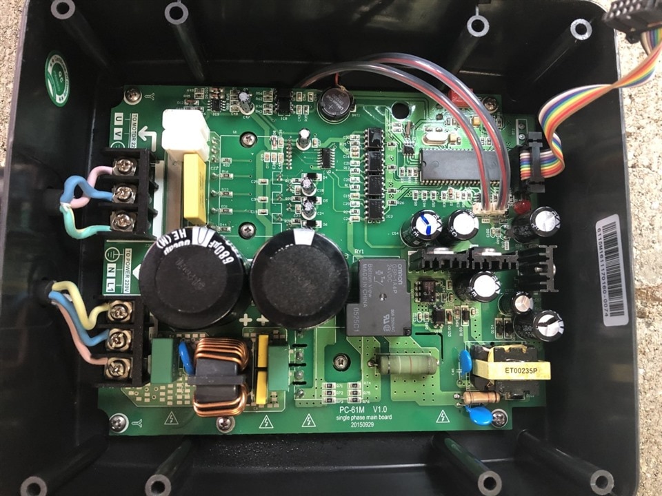
I need to replace this resistor which appears to be a 900 ohm with a % tolerance. (4 rings = Black / White / Red / Silver or Grey and around 25mm long)

I bought one with almost same features (OHMITE OX102KE Through Hole Resistor, 1K ohm, OX, 1W, ±10%, Axial, 300V) but it doesn't fit, it's far too small compare to the one I need to replace. Do you have any suggestion where to buy or how to replace it ?

I attached a picture below.

Thanks a lot

Aleximage
  • Sign in to reply
  • Cancel

Top Replies

  • jw0752
    jw0752 over 2 years ago in reply to dougw +5
    Hi Doug, I'm doing good. Glad to see so many old friends still around.
  • jw0752
    jw0752 over 2 years ago +3
    Based on my experience with this style relay it is highly probable that the resistor is across the Normally Open relay contacts and serves as a soft start to the load. As configured it would current limit…
  • Gough Lui
    Gough Lui over 2 years ago +1
    Do you have any information about the power rating? As long as the power rating of the replacement is the same or greater than the original, it doesn't really matter that it is physically smaller. You…
Parents
  • michaelkellett
    0 michaelkellett over 2 years ago

    The original resistor doesn't look like 900R to me. It looks like Black, White, Red which is 1900 ohms.

    It looks as if it has got hot, but how do you know it has failed ?

    What resistance does it measure ?

    Do you have the schematic and parts list with values  for the board - without those thingsmay go badly wrong.

    MK

    • Cancel
    • Vote Up +1 Vote Down
    • Sign in to reply
    • Verify Answer
    • Cancel
Reply
  • michaelkellett
    0 michaelkellett over 2 years ago

    The original resistor doesn't look like 900R to me. It looks like Black, White, Red which is 1900 ohms.

    It looks as if it has got hot, but how do you know it has failed ?

    What resistance does it measure ?

    Do you have the schematic and parts list with values  for the board - without those thingsmay go badly wrong.

    MK

    • Cancel
    • Vote Up +1 Vote Down
    • Sign in to reply
    • Verify Answer
    • Cancel
Children
  • Alex-andre
    0 Alex-andre over 2 years ago in reply to michaelkellett

    thx for your reply, I don't have the schematic and parts list unfortunately.

    about the ohms,don't you see 4 rings ? why do you think there is only 3?

    • Cancel
    • Vote Up 0 Vote Down
    • Sign in to reply
    • Verify Answer
    • Cancel
  • Gough Lui
    0 Gough Lui over 2 years ago in reply to michaelkellett

    Eh, isn't a black band a zero? Brown would be 1. But then I've not seen resistors start with Black bands (unless they're zero-ohm) as the first band should be the first significant digit.

    Perhaps it is discoloured or marked in some way that is a little different.

    • Cancel
    • Vote Up +1 Vote Down
    • Sign in to reply
    • Verify Answer
    • Cancel
  • michaelkellett
    0 michaelkellett over 2 years ago in reply to Gough Lui

    Sorry, Brain Fart on my part.

    I think we don't know the value of that resistor !

    092 with a silver tolerance band !

    Measure it would be best.

    Or tell us what the baord does and show a picture of more of it  - might be possible to work out what its for and thus waht value makes most sense.

    MK

    • Cancel
    • Vote Up +1 Vote Down
    • Sign in to reply
    • Verify Answer
    • Cancel
  • Alex-andre
    0 Alex-andre over 2 years ago in reply to michaelkellett

    Here is the picture of the entire board. It allows to vary the speed (power) of electrical pump. There is a timer attached to it but that on the front panel.

    image

    • Cancel
    • Vote Up +1 Vote Down
    • Sign in to reply
    • Verify Answer
    • Cancel
  • Gough Lui
    0 Gough Lui over 2 years ago in reply to Alex-andre

    Hmm. Looks like part of a relay R-C snubber ... I wonder if the capacitor is on the rear-side of the board ... there are probably a range of values that could work. It would be there to avoid the relay contacts from arcing/welding together.

    That being said, michaelkellett is right - you should measure the resistor and see what value it measures at the moment. It certainly looks like it's been hot, but not hot enough to cook to death just yet ...

    - Gough

    • Cancel
    • Vote Up +1 Vote Down
    • Sign in to reply
    • Verify Answer
    • Cancel
  • Alex-andre
    0 Alex-andre over 2 years ago in reply to Gough Lui

    Ok, will do, thanks for all the information. 

    • Cancel
    • Vote Up 0 Vote Down
    • Sign in to reply
    • Verify Answer
    • Cancel
  • Alex-andre
    0 Alex-andre over 2 years ago in reply to Gough Lui

    Rear side nothing special.

    image

    • Cancel
    • Vote Up 0 Vote Down
    • Sign in to reply
    • Verify Answer
    • Cancel
  • shabaz
    0 shabaz over 2 years ago in reply to Alex-andre

    Maybe it's for switch-on surge protection (i.e. before the motor starts fully spinning, it could be for providing less power to the motor, and then the relay kicks in). In any case, based on no further information, I too would not automatically assume it is faulty, because a bit of discoloration can be normal in such boards.

    • Cancel
    • Vote Up 0 Vote Down
    • Sign in to reply
    • Verify Answer
    • Cancel
  • michaelkellett
    0 michaelkellett over 2 years ago in reply to shabaz

    I posted a similar conclusion, but Verint ate it !

    The tracks to the resistor and the relay contacts are quite chunky and augmented by a soldered on wire, so I think the designer expected large currents.

    I agree that the resistor may well be OK.

    Any replacement should be of similar size and surge (or short term overload) capacity.

    MK

    • Cancel
    • Vote Up +1 Vote Down
    • Sign in to reply
    • Verify Answer
    • Cancel
  • Alex-andre
    0 Alex-andre over 2 years ago in reply to michaelkellett

    yes something I should have mentioned first is that a current surge from wires arc effect have conducted to dysfunction of the box and a strong smell of burn and resistor was hot.

    • Cancel
    • Vote Up 0 Vote Down
    • Sign in to reply
    • Verify Answer
    • Cancel
element14 Community

element14 is the first online community specifically for engineers. Connect with your peers and get expert answers to your questions.

  • Members
  • Learn
  • Technologies
  • Challenges & Projects
  • Products
  • Store
  • About Us
  • Feedback & Support
  • FAQs
  • Terms of Use
  • Privacy Policy
  • Legal and Copyright Notices
  • Sitemap
  • Cookies

An Avnet Company © 2025 Premier Farnell Limited. All Rights Reserved.

Premier Farnell Ltd, registered in England and Wales (no 00876412), registered office: Farnell House, Forge Lane, Leeds LS12 2NE.

ICP 备案号 10220084.

Follow element14

  • X
  • Facebook
  • linkedin
  • YouTube