element14 Community
element14 Community
    Register Log In
  • Site
  • Search
  • Log In Register
  • About Us
  • Community Hub
    Community Hub
    • What's New on element14
    • Feedback and Support
    • Benefits of Membership
    • Personal Blogs
    • Members Area
    • Achievement Levels
  • Learn
    Learn
    • Ask an Expert
    • eBooks
    • element14 presents
    • Learning Center
    • Tech Spotlight
    • STEM Academy
    • Webinars, Training and Events
    • Learning Groups
  • Technologies
    Technologies
    • 3D Printing
    • FPGA
    • Industrial Automation
    • Internet of Things
    • Power & Energy
    • Sensors
    • Technology Groups
  • Challenges & Projects
    Challenges & Projects
    • Design Challenges
    • element14 presents Projects
    • Project14
    • Arduino Projects
    • Raspberry Pi Projects
    • Project Groups
  • Products
    Products
    • Arduino
    • Avnet Boards Community
    • Dev Tools
    • Manufacturers
    • Multicomp Pro
    • Product Groups
    • Raspberry Pi
    • RoadTests & Reviews
  • Store
    Store
    • Visit Your Store
    • Choose another store...
      • Europe
      •  Austria (German)
      •  Belgium (Dutch, French)
      •  Bulgaria (Bulgarian)
      •  Czech Republic (Czech)
      •  Denmark (Danish)
      •  Estonia (Estonian)
      •  Finland (Finnish)
      •  France (French)
      •  Germany (German)
      •  Hungary (Hungarian)
      •  Ireland
      •  Israel
      •  Italy (Italian)
      •  Latvia (Latvian)
      •  
      •  Lithuania (Lithuanian)
      •  Netherlands (Dutch)
      •  Norway (Norwegian)
      •  Poland (Polish)
      •  Portugal (Portuguese)
      •  Romania (Romanian)
      •  Russia (Russian)
      •  Slovakia (Slovak)
      •  Slovenia (Slovenian)
      •  Spain (Spanish)
      •  Sweden (Swedish)
      •  Switzerland(German, French)
      •  Turkey (Turkish)
      •  United Kingdom
      • Asia Pacific
      •  Australia
      •  China
      •  Hong Kong
      •  India
      •  Korea (Korean)
      •  Malaysia
      •  New Zealand
      •  Philippines
      •  Singapore
      •  Taiwan
      •  Thailand (Thai)
      • Americas
      •  Brazil (Portuguese)
      •  Canada
      •  Mexico (Spanish)
      •  United States
      Can't find the country/region you're looking for? Visit our export site or find a local distributor.
  • Translate
  • Profile
  • Settings
Power & Energy
  • Technologies
  • More
Power & Energy
Blog Building a Smart Electronic Load | DAC and Initial Firmware (#2)
  • Blog
  • Forum
  • Quiz
  • Documents
  • Polls
  • Events
  • Mentions
  • Sub-Groups
  • Tags
  • More
  • Cancel
  • New
  • Share
  • More
  • Cancel
Group Actions
  • Group RSS
  • More
  • Cancel
EMI-Reduction-Techniques
Engagement
  • Author Author: Attila Tőkés
  • Date Created: 8 Jan 2025 6:29 PM Date Created
  • Views 431 views
  • Likes 8 likes
  • Comments 1 comment
  • esp32
  • electronic load
Related
Recommended

Building a Smart Electronic Load | DAC and Initial Firmware (#2)

Attila Tőkés
Attila Tőkés
8 Jan 2025
Hi E14 Community! Slight smile Quick update on the Smart Electronic Load project:
  
Previous blog posts:
 Building a Smart Electronic Load | Introduction (#1) 
 
I started testing the stages of the load one-by-one, starting with the R-2R DAC.
  
The DAC is now temporally only 12-bit, as I accidentally used the UART (RX/TX) pins for two of the DAC bits. To avoid glitches those 2 bits are eliminated until the next revision of the board
   
Other than that, the R-2R DAC is working mostly fine. Based on the rise times the bandwidth is around ~2 MHz:
  
image image
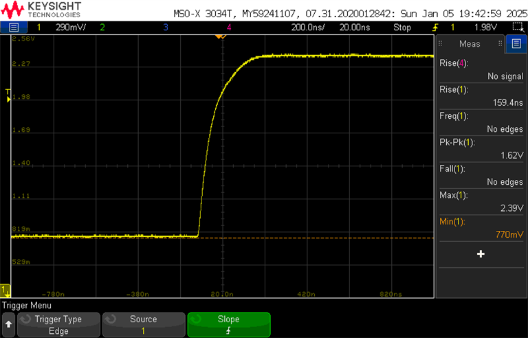
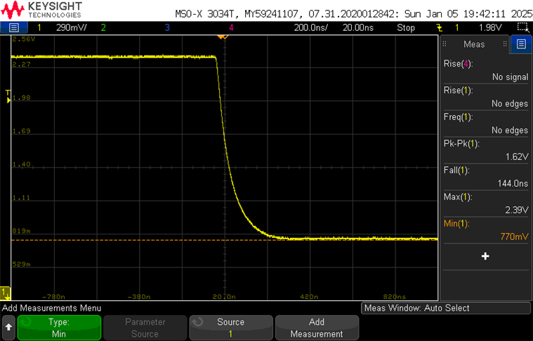
(transition between two voltages op-amp input)
  
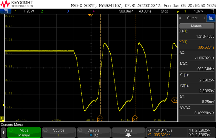
There is some over and undershoot at the op-amps output, so that probably needs a filter capacitor.
  
image image
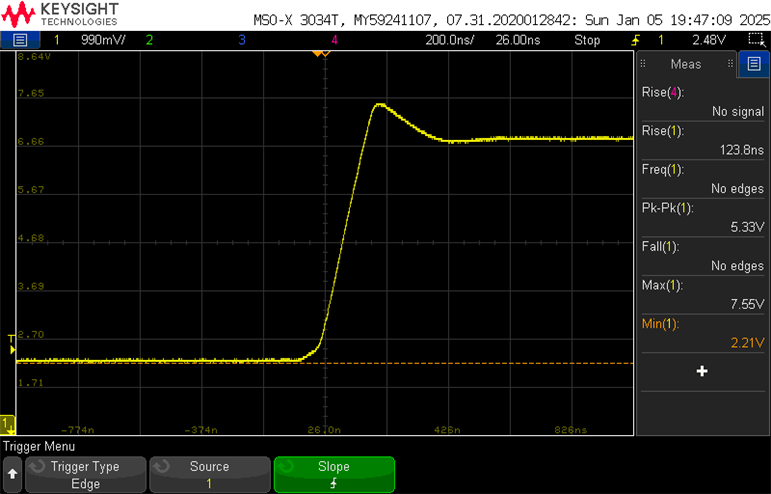
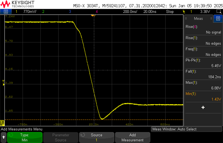
(transition between two voltages op-amp output)
  
We can also generate pulses / square(-ish Grin) waves with up-to around 1MHz duty cycle. Some filtering adjustments needed.

image image

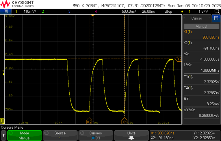
(1 MHz "square" wave with a low and high voltage value, at the op-amp input at output)
  

Thanks to michaelkellett  the load is now stable. The fix was to add a properly sized feedback capacitor to the load control op-amp. This reduces the bandwidth to a reasonable level (currently ~0.4 MHz), and resolved both the high freq oscillation at MOSFET gates and the glitches on one of the channels.
  

A first (very basic) version of the firmware is also starts getting shape. The focus is mostly on control over the REST API, and on a basic control loop. Voltage, current and temperature sensing is working, along with OTA updates. Source code on GitHub.
  

Next, I will probably sketch up some Jupyter notebooks to test the load under various conditions. For example I want to take a look at temperature curves at various power levels.
  

Bonus question: any ideas on why op-amp pins would be sensitive to digital multi-meter probing, and on how to avoid the problem? I found that some parts of the circuit are sensitive to multi-meter probing (in V/mV mode), and also to finger touches.
  
The problem is most prominent on the non-inverting pin(s) of the DAC op-amp, but in some degree is also present on the inverting (more) and non-inverting pins (less) of the current sense op-amp.
image
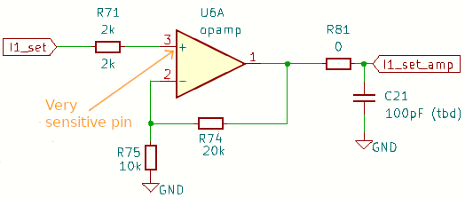
If I probe the above pin (relative to GND) the load current shoots up (triggers the over current protection of the power supply) and there is even some audible noise getting to the PC speakers.
  
In my mind the multi-meter should act like a ~10 MOhm resistor plus maybe some capacitance, and I cannot image that having such drastic effects on the circuit. Another theory would be that we are picking up some noise with the probe leads.
  
For the DAC I though to reduce the values of the resistors so that more current will flow, and thus the circuit would be less sensitive to noise.
  
Hope you enjoyed this post! Sunglasses
  • Sign in to reply

Top Comments

  • dougw
    dougw 7 months ago +1
    Pin 3 is high impedance - its voltage should be virtually the same as measuring on the other side of R71. For pin 2 I think you are right - the sensitivity should decrease as R74 and R75 decrease. A…
  • dougw
    dougw 7 months ago

    Pin 3 is high impedance - its voltage should be virtually the same as measuring on the other side of R71.

    For pin 2 I think you are right - the sensitivity should decrease as R74 and R75 decrease. A small compensation cap across R74 might help but also might hurt bandwidth.

    • Cancel
    • Vote Up +1 Vote Down
    • Sign in to reply
    • More
    • Cancel
element14 Community

element14 is the first online community specifically for engineers. Connect with your peers and get expert answers to your questions.

  • Members
  • Learn
  • Technologies
  • Challenges & Projects
  • Products
  • Store
  • About Us
  • Feedback & Support
  • FAQs
  • Terms of Use
  • Privacy Policy
  • Legal and Copyright Notices
  • Sitemap
  • Cookies

An Avnet Company © 2025 Premier Farnell Limited. All Rights Reserved.

Premier Farnell Ltd, registered in England and Wales (no 00876412), registered office: Farnell House, Forge Lane, Leeds LS12 2NE.

ICP 备案号 10220084.

Follow element14

  • X
  • Facebook
  • linkedin
  • YouTube