

.jpg)

Epishine is about to launch this interesting light energy harvesting (LEH) kit and has provided some early samples for evaluation.
Unboxing
Here is an unboxing showing what might be expected in the kit:
LEH Kit Features

Basically the LEH module is a light harvesting power supply that can deliver up to 20 mA and be set to output any one of 16 voltages in 0.1 V increments between 1.8V and 3.3V.
The challenge for any solar power system is to convert variable low voltage and highly variable current from a solar cell into a useful regulated voltage, and this Epishine module does exactly this, including taming the highly variable voltage on a super capacitor.
Solar cells are a compelling alternate energy source even though they are not very efficient because sunlight is essentially free, at least until some greedy politician decides it should be taxed. This module takes advantage of excess light in an indoor setting.
Note that this solar cell cannot deliver enough current to supply 20 mA continuously, so loads like this would be intermittently driven, or powered with the help of a battery.
This regulated output voltage is selected by 4 switches that encode to a 4 bit binary number to select one of 16 output voltages.
The module gets its power from a super capacitor which gets its charge from either the onboard solar cell or an external primary backup battery.
The battery keeps the capacitor above its dropout voltage once the output has turned on.
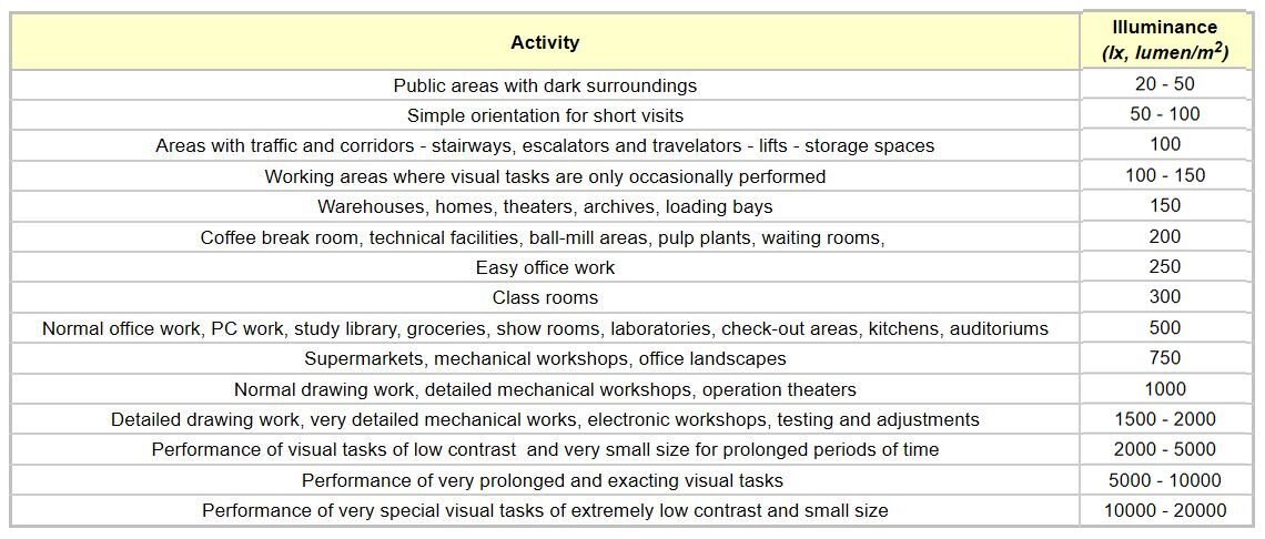
The solar cell circuit will charge the super cap in any light level above 70 lux until it reaches 4.5 V. This light level is below typical room lighting levels. At this level the capacitor charges very slowly, somewhere around 1 mV / min.
To provide some perspective of how much light this is, here is a list of light levels in typical environments:
The regulated output turns on when the super cap voltage goes above 3.92V and of course if a load is applied, it will only charge the capacitor if the load power is less than the solar cell can supply.
The solar cell output is boosted by an efficient circuit that turns on when the solar cell voltage exceeds about 350 mV. This allows the super cap to be charged to 4.5 V assuming no load.
The regulated output voltage will turn off when the super cap voltage dips below about 3.1V. However, between 3.6V and 3.1V the output voltage does not stay at 3.3V (assuming 3.3V has been selected on the switches) it will track the supercap voltage until the output turns off at 3.1V.
Solar Charge - Discharge Cycle
Here is an image showing what the output voltage (green trace) does as the capacitor charges up past the turn on voltage and discharges to the dropout voltage.

The little excursion from constant voltage regulation both up and down just before dropout is consistent with how this module is expected to work.
Charging Current
Next I wanted to look at how much charging current is supplied by the solar cell under various lighting conditions, but there is a circuit that boosts the solar cell voltage, so it can charge the super capacitor to a voltage that exceeds the solar cell voltage,.... so I also wanted to know how the current changes with voltage on the super capacitor.
To do this I adjusted a resistive load on the super capacitor that kept the voltage constant at each voltage of interest. If the voltage is constant, then the current going to the capacitor is equal to the current leaving the capacitor and I only needed to measure the current through the load resistor to know how much current was being supplied by the solar cell and its boost circuit. I actually measured the resistance and voltage to calculate the current.
Here is a plot of the charging current at each of 4 voltages versus 8 different light levels shining on the solar cell:

These curves don't tell us much that is unexpected - the current generally increases as the light level goes up and you can get some idea of how long the capacitor takes to charge up because:
i/C = dv/dt
So for example at 850 Lux the charging current is 1.5 mA. The capacitance is 0.4 F. Assuming the delta time is 1 s. This implies the cap is charging at a rate of 3.75 mV/s, or 4.4 minutes per volt.
At light levels below 200 Lux, it can take a long time to charge up the capacitor.
Incidentally when the output turns on (above 3.92 V) the output regulator draws enough current that 230 Lux is needed to maintain capacitor voltage, even without any other load (although I did have a voltmeter connected to the capacitor, which is a small load.
Before the output turns on, 70 Lux is enough to start charging the capacitor.
I will throw in the same curve showing power instead of current to provide a better feel for what kinds of load can be driven by this small solar cell at various light levels:

Battery Backup
If the primary battery is connected, it will basically keep the super cap charged enough to ensure the regulated output stays on. It does this by periodically turning on a battery boost circuit when the supercap discharges close to 3.6 V until it charges up to about 3.9V.
If the battery falls below 1.4V it will cease to be used for charging the super cap.
This behaviour is shown in the oscilloscope screen shot below:

Note that the battery voltage is present before the output turns on, but it is not used to charge the capacitor until the capacitor has been charged by the solar cell to a high enough voltage to turn on the output.
The load in this case is more than the solar cell can handle, so the capacitor tends to discharge, however the battery booster kicks in before the capacitor discharges to the point that the output drops out.
The battery circuit will periodically charge the capacitor until the battery voltage drops below 1.4 V. The battery voltage may be as high as 5 V, although I only used 1.5 V in this example to show that is works at 1.5 V but not at 1.4 V.
Efficiency
Efficiency is a big topic for solar cells because it affects cost and space requirements. There are theoretical limits to solar cell efficiency of about 32% as shown in this plot:

Most practical solar cell technologies struggle to get close to 20%. The solar cell technology in this module is not aimed at the ultimate efficiency - it is aimed at being thin and flexible. The power conversion circuitry on the other hand is nicely efficient.
I am taking a stab at calculating light-to-electrical efficiency, but am sot sure I have it all straight. Converting Lux to Watts is not straightforward.
This solar cell is 5.08cm x 5.84cm = 0.0029677 sq m.
At 16,000 Lux the light flux reaching the surface of the solar cell is about 126.4 lm/W.
efficiency = 100 * power/(flux * area) = 100 * 0.0075 / 0.375 = 2%
I question my calculation here - it seems a little low.
I did fool around a bit looking at how much light is reflected versus absorbed as an indication of efficiency, but it was more to demonstrate that some of the losses are due to light reflecting off the solar cell surface. There are other losses in PV conversion that I can't measure.
Fair warning - this video is a little glacial.
Practical Operation
The video below shows this tiny little solar module powering a complete microcontroller system with 3 LEDs, a temperature sensor and a graphical LCD.
When the 3 LEDs are on, the system requires 33 mA. When only 1 LED is on, the system consumes 11 mA.
Even though this example is feeding 3.3 V in to a USB power port, the microcontroller still works when the Epishine module turns on its output.
Output Current
This chart is of the most interest to potential users. It shows how much output current can be drawn continuously at various light levels.

This chart indicates that the module can supply over 1.5 mA continuously if the illumination exceeds 10,000 Lux.
Note that the light meter readings in all of my data may be slightly off because the light source is not uniform and the light meter cannot see exactly what the solar cell sees. The light meter itself has up-to-date calibration.
Workmanship
I just have to comment on the one tiny little jumper on the card.

The diameter of this wire jumper is much smaller than the 0402 resistor width.
My hat is off to whoever put that jumper on - it is an amazingly neat job.
Test Setup
My test setup kept growing and morphing as I got more into the testing different aspects This picture is a snapshot of some of it.
I shot 23 videos during the testing, and spent a lot of time not only setting up and shooting, but also trying to cull it all down to a palatable size.
Testing a module like this is a time consuming exercise, it just takes a lot of time to run a bunch of charge-discharge cycles, especially when you have to tweak the setup and repeat it all over again - several times.

Gratuitous cat video, in case it is more dynamic than watching a capacitor charge up...
Summary
The Epishine LEH development kit is a flexible and efficient power supply implementation handling multiple power sources and including selectable regulated output voltages. Even the card and solar cell themselves are physically flexible. Epshine have created a somewhat simplified implementation of the e-peas Semiconductors AEM10941 energy manager chip. This is a good thing as the chip is quite complex. However the flexibility that is available still requires a bit of a learning curve to master.
Overall I am impressed with the functionality and efficiency embodied in this module. It shows what is possible when you have a specialized requirement for low power light scavenging. This Epishine module does a good job of taking the highly variable solar cell output and highly variable super capacitor voltage and efficiently delivering a precisely regulated output voltage with predictable performance.
I could see it being used in LoRa applications, or even BLE applications or EnOcean type IoT.
Relevant Links:
https://e-peas.com/product/aem10941/
https://e-peas.com/wp-content/uploads/2020/04/DS_AEM10941.pdf
https://e-peas.com/wp-content/uploads/2020/04/PB_AEM10941_REV1.3.pdf
Solar Energy Harvesting with Epishine Flexible Solar Cell - Pt 1: intro
Early-Access Review: Epishine Light Energy Harvesting Module Evaluation Kit
Top Comments