


I've recently designed a 650 Watt DC-DC Buck Converter for a satellite and I chose to use GaN FETs for both the series switch and for the synchronous rectifier. For this power range, I could not believe how small these new generation 5, chip-scale GaN FETs are that are made by EPC Corp. A chip-scale device is basically the individual FET die, cut from the GaN wafer, but not put into a package such as the typical TO-220. Instead, the FET gets passivated, which is a type of covering to protect the top-side of the die. The passivation is for the protection of the GaN structures, with leads that protrude thru the passivation layer. The GaN FET process is similar to the structure of a Silicon IC, or a PC Board and can have many layers with the GaN placed over the Silicon substrate. The chip-scale packaging allows for very low lead inductance and efficient cooling thru the top-side (Silicon substrate side) of the FET. GaN is useful for space applications in that it has a high immunity to un-commanded turn-on by ionizing radiation. This is due to it's wide bandgap compared to Silicon.
The GaN FET I used is the EPC2218, with actual size of just 4.1 x 1.6 mm (0.16" x 0.063") and there were two FETs used, one for the series switch and one for the synchronous rectifier. This FET is rated at 100V, 60A, and has an RDSon of just 3.2 mΩ. I ran these FETs at full 667 watt output power on the bench with no heatsink and no fan and they did get somewhat hot, about 120° C, but these GaN FETS can take about 300° C without damage. However, the solder would melt if it was run that hot. The FETs have an epoxy underfill to avoid them breaking loose from their solder pads and moving if the solder ever melted. The input was 40 VDC and the output was 29 VDC. The measured efficiency was 97.8% which included the loss in the inductor and pcb traces. I chose a modest switching frequency of 500 KHz, but these GaN FETs switch so fast, they can easily be run at 2-3 MHz or higher.
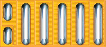
The SMD leads are oval-shaped solder bumps on the FET as can be seen in the first photo of the bottom-side (lead-side) of an EPC2218 FET. The GaN's lead bump side becomes the bottom-side of the FET and gets soldered to the PCB, similar to the way a BGA gets soldered, except that the leads are oval and not spherical. The top-side of the FET is, therefore, from the bottom-side (substrate) of the GaN wafer. The substrate, or bottom layer of the GaN FET is Silicon upon which GaN features are deposited in a complex manufacturing process. The Silicon substrate allows the devices to be manufactured using standard Silicon IC photolithographic processes and equipment. The top of the GaN FET is actually from the die's substrate and since it has no features etched into it, it doesn't need any passivation for protection. It's from the bottom of the Silicon wafer upon which the GaN features are deposited and is doped Silicon. Here's a link to the EPC2218 datasheet: https://epc-co.com/epc/Portals/0/epc/documents/datasheets/epc2218_datasheet.pdf
The last photo is of an EPC90123 Evaluation Board using the EPC2218 GaN FETs. The FETs can be seen in the red box with the white arrow pointing to one of the two FETs. The entire board is only 50 x 50 mm (2" x 2"). As you can see, these FETs are tiny, especially given the power they're converting. The EPC90123 eval board photo is from the EPC90123 Eval Board user's guide and does not show the CoilCraft inductor I used, which was P/N: AGP4233, 6.8 uH. The DC-DC Converter's full load output current is over 23 amps DC at 29 VDC, for 667 watts output power. The eval board requires the user to supply their own inductor and output cap. I used a 10 uF, 50 V, MLCC cap, a TDK P/N: CKG57NX7R2A106M500JJ. I should also mention that the EPC90123 eval board can be configured as either a Buck or as a Boost converter. Additionally, it has provision for heatsinking.
As much as I would encourage everyone to experiment with GaN FETs, I don't recommend breadboarding your circuit. Due to the high switching frequencies involved, it's critical that a PC Board is laid-out for your design with good high-frequency design and layout technique used. The EPC webpage for their EPC90123 Eval Board is a good place to start.
The link is: https://epc-co.com/epc/Products/DemoBoards/EPC90123.aspx and this page has links to the Schematic, Gerber files, the Quick Start Guide, a Bill of Material, and more.
 |
 |


