element14 Community
element14 Community
    Register Log In
  • Site
  • Search
  • Log In Register
  • Community Hub
    Community Hub
    • What's New on element14
    • Feedback and Support
    • Benefits of Membership
    • Personal Blogs
    • Members Area
    • Achievement Levels
  • Learn
    Learn
    • Ask an Expert
    • eBooks
    • element14 presents
    • Learning Center
    • Tech Spotlight
    • STEM Academy
    • Webinars, Training and Events
    • Learning Groups
  • Technologies
    Technologies
    • 3D Printing
    • FPGA
    • Industrial Automation
    • Internet of Things
    • Power & Energy
    • Sensors
    • Technology Groups
  • Challenges & Projects
    Challenges & Projects
    • Design Challenges
    • element14 presents Projects
    • Project14
    • Arduino Projects
    • Raspberry Pi Projects
    • Project Groups
  • Products
    Products
    • Arduino
    • Avnet & Tria Boards Community
    • Dev Tools
    • Manufacturers
    • Multicomp Pro
    • Product Groups
    • Raspberry Pi
    • RoadTests & Reviews
  • About Us
    About the element14 Community
  • Store
    Store
    • Visit Your Store
    • Choose another store...
      • Europe
      •  Austria (German)
      •  Belgium (Dutch, French)
      •  Bulgaria (Bulgarian)
      •  Czech Republic (Czech)
      •  Denmark (Danish)
      •  Estonia (Estonian)
      •  Finland (Finnish)
      •  France (French)
      •  Germany (German)
      •  Hungary (Hungarian)
      •  Ireland
      •  Israel
      •  Italy (Italian)
      •  Latvia (Latvian)
      •  
      •  Lithuania (Lithuanian)
      •  Netherlands (Dutch)
      •  Norway (Norwegian)
      •  Poland (Polish)
      •  Portugal (Portuguese)
      •  Romania (Romanian)
      •  Russia (Russian)
      •  Slovakia (Slovak)
      •  Slovenia (Slovenian)
      •  Spain (Spanish)
      •  Sweden (Swedish)
      •  Switzerland(German, French)
      •  Turkey (Turkish)
      •  United Kingdom
      • Asia Pacific
      •  Australia
      •  China
      •  Hong Kong
      •  India
      •  Japan
      •  Korea (Korean)
      •  Malaysia
      •  New Zealand
      •  Philippines
      •  Singapore
      •  Taiwan
      •  Thailand (Thai)
      •  Vietnam
      • Americas
      •  Brazil (Portuguese)
      •  Canada
      •  Mexico (Spanish)
      •  United States
      Can't find the country/region you're looking for? Visit our export site or find a local distributor.
  • Translate
  • Profile
  • Settings
Power & Energy
  • Technologies
  • More
Power & Energy
Blog Low Voltage Step-Down Converter TPS54A20 - First Check
  • Blog
  • Forum
  • Quiz
  • Documents
  • Polls
  • Events
  • Mentions
  • Sub-Groups
  • Tags
  • More
  • Cancel
  • New
  • Share
  • More
  • Cancel
Toptech-Voices
Group Actions
  • Group RSS
  • More
  • Cancel
Engagement
  • Author Author: Jan Cumps
  • Date Created: 2 Aug 2016 8:43 PM Date Created
  • Views 4516 views
  • Likes 6 likes
  • Comments 25 comments
  • dc to dc regulator
  • switching regulator
Related
Recommended

Low Voltage Step-Down Converter TPS54A20 - First Check

Jan Cumps
Jan Cumps
2 Aug 2016

I received an evaluation board for the TPS54A20 DC/DC converter from TI.

This switcher is specific for low voltage designs. The output range is 0.5 - 2 V.

That's a very narrow range. In that range it can deliver 10 A, with a typical input of 12 V.

Efficiency is in the lower-to-mid 80%.

With a switch frequency of 2 MHz (more on that later) it allows for small passive components and a condensed footprint of the whole stepdown module.


image

The reason that I want to review this particular converter is because it's a two-phase type.

TI specifies it's in essence a 4 MHz design because of this. I'll validate if that's sales lingo or truth.


There's a new regulation in the US that stipulates that I have to disclose that I received this board from Texas Instruments. I don't like that. It's none of your business, and anyways, it's not a product review or endorsement. It's the comments and explanation of an interested person.

I don't like to be told by a gouvernment what legal clauses I should put in an amateur blog.

I don't put this disclosure here because I have the intention to comply.

Only to avoid that TI gets sanctioned.


Basic Specs


The full specs of the converter are available on the TPS54A20 landing page

The parameters are all focused on getting a small-footprint (both pcb real-estate and height) and reasonable efficient conversion from 12 V in to maximum 2 V out.


  • Output Voltage Range: 0.5 - 2 V
  • Output Current: 10 A
  • Typical switching frequency: 2 MHz (per phase)
  • Input Voltage Range: 8 - 14V
  • Max. efficiency is just above 90% in the IC datasheet. The evaluation board has a maximum efficiency of 84.7%


Because the passives required by the converter are really small, the converter and it's surrounding components can easily be mounted on the underside of a PCB.

On the evaluation board, the tallest components are the two coils. They are MLA-FY12NR22N-M3-RU. They have a height of 1.2 mm.


Two-Phase? Series Capacitor?


This is the reason why I'm interested in this converter. It's a particular design that splits into two converters that are phase shifted.


image

Image from the product landing page


The name TI gives to this design is "two-phase, synchronous series capacitor buck converter".

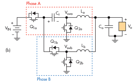
In this design you have one inductor per phase. You can find an explanation of the concept here.

The image below is taken from that link. Check the topology section of the datasheet for a per-phase breakdown of the circuit.
image


I can't explain it better than what Paul Pickering tells us in that link.

In essence, the capacitor Ct (the Series Capacitor"), because of where it's positioned in the circuit, has half VIN over it in steady state.

So one component deals with stepping down the input voltage by half, with theoretically no energy loss.

What remains abstracts to two out-of-phase buck converters.

Leave your better explanation of the design in the comments.


Evaluation Board Configuration


The board is configured for 1.2 V output and 2 MHz switching frequency.

Input voltage is between 9.2 and 14 V, although 9.4 V is required initially to prime the converter.

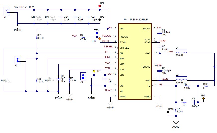
Below is the schematic of the switching core.

I've left out the output filters and the transient load circuit (this merits a separate blog).
 

image


This is virtually the same as the typical application from the datasheet.

The frequency is set by the resistor R1 connected to SS/F SEL. See this table to find out how to translate frequency, soft start time and hiccup (related to overcurrent recovery) time against resistor value.

On the evaluation moule, R1 is not populated, so these are the parameters applicable for that setup:

RSS/FSEL (kΩ)FOSC (MHz)FSW (MHz)Soft Start Time (µs)Hiccup Time (ms)
Open4251232.8


This is a light touch on the subject. In the next posts I'll go deeper into the topology and the design choices made on the EVM board.

And maybe the first measurements...


Related Blog
Low Voltage Step-Down Converter TPS54A20 - First Check
Low Voltage Step-Down Converter TPS54A20 - Series Capacitor
  • Sign in to reply

Top Comments

  • Jan Cumps
    Jan Cumps over 10 years ago in reply to jc2048 +2
    jc2048 , that's no hijack. That's all cool things. Thank you! I'll have to purchase a new chip though. Even though I tried to be as careful as possible, and used a magnifying glass while probing, I damaged…
  • Jan Cumps
    Jan Cumps over 9 years ago in reply to Jan Cumps +2
    The outcome is as expected. I've put my scope probes on probe points A and B - left and right side of the series capacitor. My input signal is 10V. The capture below is: Yellow: probe point A; Bounces…
  • Jan Cumps
    Jan Cumps over 9 years ago in reply to Jan Cumps +2
    Fixed! It works
  • Jan Cumps
    Jan Cumps over 10 years ago in reply to jc2048

    Yep. Sounds plausable.

    • Cancel
    • Vote Up 0 Vote Down
    • Sign in to reply
    • More
    • Cancel
  • jc2048
    jc2048 over 10 years ago

    "Leave your better explanation of the design in the comments."


    Not sure this is a better explanation, but this is the way I'd look at it.


    When Q1a is on, current flows through the capacitor and coil La from Vin - charge accumulates on the capacitor, the coil establishes a magnetic field, and the load is powered. When Q1a turns off, and Q2a turns on, the coil La keeps the current to the load going, gradually depleting its magnetic field (because that's what coils do). At the same time,  Q1b turns on and the energy in the capacitor (notice that the negative of the capacitor is now connected to ground by Q2a) is used as the power source for the other phase, with Lb establishing its field and driving current into the load. After a time, Q1b is turned off and Q2b is turned on, and Lb keeps the current going by retrieving energy from its field.


    The steady state average (there has to be some ripple) voltage on the cap is half the supply because during one phase it hangs from the supply and for the other it sits on ground. If the supply voltage to the coils is to be the same for both phases, that can only happen if the capacitor voltage splits the supply in two (the voltage driving La is the supply minus the capacitor voltage, the voltage driving Lb is the capacitor voltage). I'm not clear whether that happens naturally by virtue of the circuit or whether they have to force it through monitoring the currents and controlling the switching. I think it self-adjusts - if the capacitor voltage increases, the current in La goes down, the current in Lb goes up, that drains the capacitor more than it charges resulting in the voltage coming down. Does that sound reasonable?

    • Cancel
    • Vote Up +1 Vote Down
    • Sign in to reply
    • More
    • Cancel
  • Jan Cumps
    Jan Cumps over 10 years ago

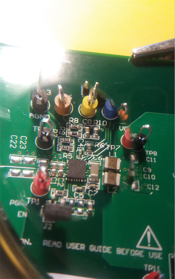
    Object under test.

    1.2 V, 1 A flowing trough the load. I'm trying to capture how the series capacitor on its own steps down the source voltage to half value.


    image


    (also posting this because I think it's a sweet photo)

    (power cables courtesy jw0752)

    • Cancel
    • Vote Up +1 Vote Down
    • Sign in to reply
    • More
    • Cancel
  • Jan Cumps
    Jan Cumps over 10 years ago in reply to jw0752

    John, yes. Switching converters are often very inventive circuit designs, I think.

    Understanding those always requires me to really understand what's happening under the hood.

    The datasheet contains an explanation of what happens during both phases, with drawings.

    I find the use of that series capacitor genious. For switch mode experts, this is probably bread and butter.

    For me it's a piece of art image

    • Cancel
    • Vote Up 0 Vote Down
    • Sign in to reply
    • More
    • Cancel
  • jw0752
    jw0752 over 10 years ago

    Hi Jan,

    This looks like a fascinating circuit. I will look forward to learning more in your subsequent posts.

    John

    • Cancel
    • Vote Up +1 Vote Down
    • Sign in to reply
    • More
    • Cancel
<
element14 Community

element14 is the first online community specifically for engineers. Connect with your peers and get expert answers to your questions.

  • Members
  • Learn
  • Technologies
  • Challenges & Projects
  • Products
  • Store
  • About Us
  • Feedback & Support
  • FAQs
  • Terms of Use
  • Privacy Policy
  • Legal and Copyright Notices
  • Sitemap
  • Cookies

An Avnet Company © 2026 Premier Farnell Limited. All Rights Reserved.

Premier Farnell Ltd, registered in England and Wales (no 00876412), registered office: Farnell House, Forge Lane, Leeds LS12 2NE.

Follow element14

  • X
  • Facebook
  • linkedin
  • YouTube