

.jpg)

Last year, I asked a question on how to best maintain power long enough to allow my 3D Printer SBC to power off properly: /technologies/power-management/f/forum/54285/maintain-power-long-enough-for-sbc-to-power-down
The easiest solution was simply to add a very large capacitor on the 24V to 5V step down converter, while creating a single transistor active low signal for the SBC to be informed about power loss.
While this proved effective for the SBC to have time to properly shutdown, there was an issue on the next power on, when 24V was coming back.
Indeed, because of the large capacitor, there wasn't a clear disappearance of the +5V power signal and the SBC would not power back on reliably. Basically, if I waited a week between power off and power on, it would work, but not if it was only two or three days.
This lead to another question where I discussed about using a relay to properly disconnect the SBC from the +5V rail, respecting the following timing diagram:

shabaz noted that doing it all with analog circuitry would have been quite complex and not flexible at all, so I went with the microcontroller option and used a PIC16F628A that had been sitting in my inventory for many years.
As I wanted to change the PowerOff delay without reprogramming the microcontroller, I decide to use a simple voltage divider with a potentiometer. The voltage is usually converted to binary with an ADC, but in my case, the PIC16F284A does not have one. I could have bought a different microcontroller, but then I remembered that this one has a comparator and a programmable voltage reference.
By configuring the comparator to use one pin as its first input and the same pin as where the internal voltage reference is output as its other input, by varying VRef repeatedly, this gives me a “Poor man’s ADC” that is tested in this video:
Sure, it’s only 4 bits, it’s not full scale as VRef is not full scale, but it’s more than enough for this use case.
For reference, here is the “Poor man’s ADC” code:
uint8_t readExpectedDelay()
{
    // As there is no ADC on the 16F628A, we use the comparator module to
    // compare VREF to the analog voltage on RA1
    // Changing VREF repeatedly until the comparison tells us RA1 is above VREF
    // gives us 16 discrete levels from the analog voltage, aka "poor man's ADC".
    uint8_t result = 0;
    do
    {
        VRCONbits.VR = result;
        __delay_us(10 + 5);  // 10 for VREF settling + 5 for comparator update
        result++;
    }
    while ((result <= 0x0F) && (!CMCONbits.C2OUT));

    return result;
}
To reduce component count, the PIC is configured to internally tie the MCRL pin to VDD and to use the internal oscillator at 48kHz. This very low oscillator speed allows very long delays from TMR0, thus reducing the complexity of the code to be written.
With this setup, there is also the need for the SBC to provide a valid “PiRunning” signal to the microcontroller.
Ideally, one would use the Status Led (the green one), as it is only on when the Allwinner H3 is running. Sadly, PA15 is directly routed to the LED and is not surfaced on the 40-pin connector.
As soldering a piggy back signal on such a small LED is not possible for me, I went another route, this time leveraging the Armbian image running on the OrangePi.
It is indeed possible to control the GPIOs via command line and so I went as far as writing systemd services that turn on and off a dedicated pin on the 40-pin connector. Note that it MUST turn the pin back off because the pin electrical state is kept even when the SOC is no longer running by itself.
There is a concept called “Device Tree Overlay” in the Linux kernel which would have allowed not using a service at all, but it’s not activated on the armbian image for OrangePi.
There is also a service that monitors the “PowerLoss” signal so that it issues the “poweroff” command when it gets signaled.
Here are their contents:
/etc/systemd/system/wait_for_gpio7.service
[Unit]
Description=GPIO7 waiter

[Service]
Type=exec
User=octo
ExecStartPre=/usr/local/bin/gpio mode 7 INPUT
ExecStart=/usr/bin/wait_for_gpio7.sh
Restart=on-failure

[Install]
WantedBy=multi-user.target
/etc/systemd/system/indicate_alive_on_gpio.service
[Unit]
Description=Signals board is alive on a GPIO pin

[Service]
Type=exec
User=octo
ExecStartPre=/usr/local/bin/gpio mode 23 out
ExecStart=/usr/local/bin/gpio write 23 1
RemainAfterExit=yes
ExecStop=/usr/local/bin/gpio write 23 0

[Install]
WantedBy=multi-user.target
As you can see, the watcher service calls a script in /usr/bin because the script itself is a bit more complex than simply starting a command. And this also has the advantage of not requiring to issue systemctl daemon-reload every time a change is required.
Here is the script:
/usr/bin/wait_for_gpio7.sh
#!/bin/bash

# watch for PA6 to change (gpio 7)
set previousState=""

while true;
do
        currentState=`/usr/local/bin/gpio read 7`
        if [ ! -z $previousState ]; then
                if [ $currentState -ne $previousState ]; then
                        if [ $currentState -eq 1 ]; then
                                echo "GPIO7 signaled power loss, shutting down!"
                                poweroff
                        fi
                fi
        fi
        previousState=$currentState

        sleep 1
done
This requires to have a binary called gpio that can be created from the following repository: https://github.com/orangepi-xunlong/wiringOP
With all this setup, I was expecting everything to work but sadly, it did not, as I reported here:
/technologies/experts/f/forum/55735/single-mosfet-level-shifter-does-not-appear-to-work
This was solved by replacing the bidirectional shifter with a simple pull-down transistor as all is needed is to shift the levels in one direction, not both. This works much more reliably.
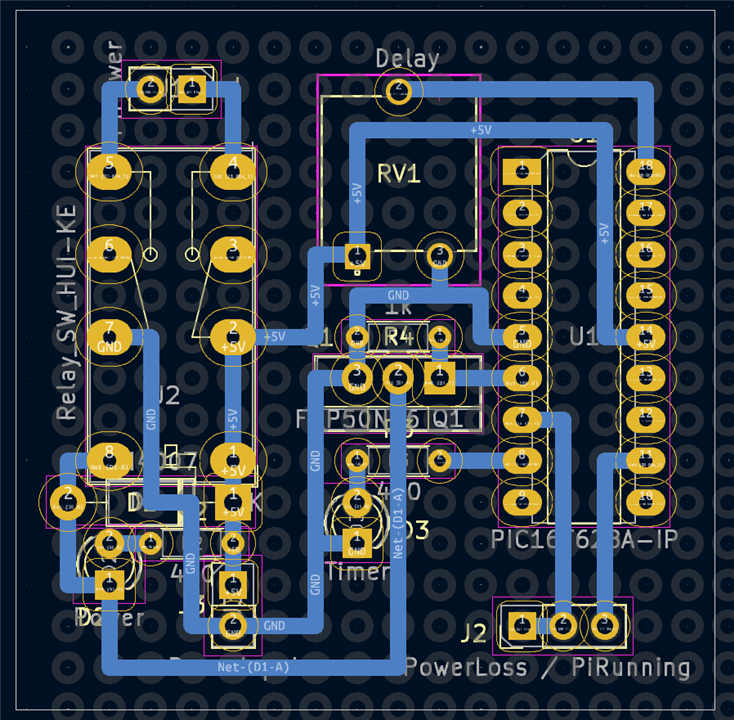
As I did not fancy creating and ordering a custom PCB just for this one off small project, I went with my existing prototyping boards, simply using KiCad to create both the schematic and the grid aligned PCB:
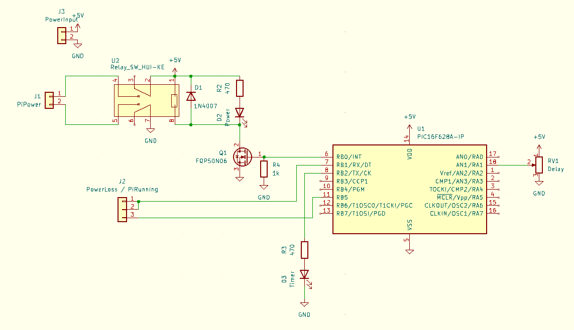
The only thing not shown here is an afterthought where I added a 1W resistor across the relay NC pins so that the huge capacitor from the step down converter is drained quickly after everything is powered off. This avoids a potential safety hazard with this high current source, should anyone touch the +5V leads by accident.
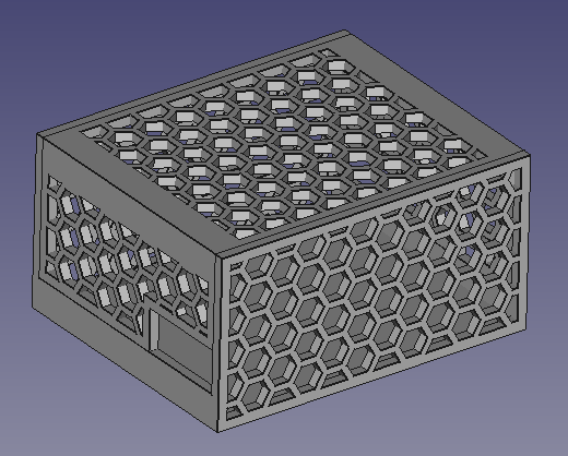
And now I finally have a system that properly manages power supply for the OrangePi, meaning that I could also create a nice box for it in FreeCAD before printing it:
If you are interested, I have placed the project source files here: https://github.com/obones/OrangePiPower
Do not hesitate to ask questions or tell me if there are files missing in the above repository.
