element14 Community
element14 Community
    Register Log In
  • Site
  • Search
  • Log In Register
  • About Us
  • Community Hub
    Community Hub
    • What's New on element14
    • Feedback and Support
    • Benefits of Membership
    • Personal Blogs
    • Members Area
    • Achievement Levels
  • Learn
    Learn
    • Ask an Expert
    • eBooks
    • element14 presents
    • Learning Center
    • Tech Spotlight
    • STEM Academy
    • Webinars, Training and Events
    • Learning Groups
  • Technologies
    Technologies
    • 3D Printing
    • FPGA
    • Industrial Automation
    • Internet of Things
    • Power & Energy
    • Sensors
    • Technology Groups
  • Challenges & Projects
    Challenges & Projects
    • Design Challenges
    • element14 presents Projects
    • Project14
    • Arduino Projects
    • Raspberry Pi Projects
    • Project Groups
  • Products
    Products
    • Arduino
    • Avnet Boards Community
    • Dev Tools
    • Manufacturers
    • Multicomp Pro
    • Product Groups
    • Raspberry Pi
    • RoadTests & Reviews
  • Store
    Store
    • Visit Your Store
    • Choose another store...
      • Europe
      •  Austria (German)
      •  Belgium (Dutch, French)
      •  Bulgaria (Bulgarian)
      •  Czech Republic (Czech)
      •  Denmark (Danish)
      •  Estonia (Estonian)
      •  Finland (Finnish)
      •  France (French)
      •  Germany (German)
      •  Hungary (Hungarian)
      •  Ireland
      •  Israel
      •  Italy (Italian)
      •  Latvia (Latvian)
      •  
      •  Lithuania (Lithuanian)
      •  Netherlands (Dutch)
      •  Norway (Norwegian)
      •  Poland (Polish)
      •  Portugal (Portuguese)
      •  Romania (Romanian)
      •  Russia (Russian)
      •  Slovakia (Slovak)
      •  Slovenia (Slovenian)
      •  Spain (Spanish)
      •  Sweden (Swedish)
      •  Switzerland(German, French)
      •  Turkey (Turkish)
      •  United Kingdom
      • Asia Pacific
      •  Australia
      •  China
      •  Hong Kong
      •  India
      •  Korea (Korean)
      •  Malaysia
      •  New Zealand
      •  Philippines
      •  Singapore
      •  Taiwan
      •  Thailand (Thai)
      • Americas
      •  Brazil (Portuguese)
      •  Canada
      •  Mexico (Spanish)
      •  United States
      Can't find the country/region you're looking for? Visit our export site or find a local distributor.
  • Translate
  • Profile
  • Settings
Power & Energy
  • Technologies
  • More
Power & Energy
Forum Raspberry Pi HAT
  • Blog
  • Forum
  • Quiz
  • Documents
  • Polls
  • Events
  • Mentions
  • Sub-Groups
  • Tags
  • More
  • Cancel
  • New
Actions
  • Share
  • More
  • Cancel
Forum Thread Details
  • State Verified Answer
  • Replies 5 replies
  • Answers 1 answer
  • Subscribers 286 subscribers
  • Views 802 views
  • Users 0 members are here
  • power_management
  • raspberry pi
  • voltage
  • amperage
Related

Raspberry Pi HAT

thorleif@tjweb.no
thorleif@tjweb.no over 7 years ago

I'm trying to create a circuit in Eagle for a RPi HAT. Currently I am stuck at finding a reliable circuit which meets my needs for power.


The HAT is going to contain a 16ch PWM controller, gyro, compass, accel and a power sensing and voltage sensing circuit. All who speaks over 3v3 i2c.


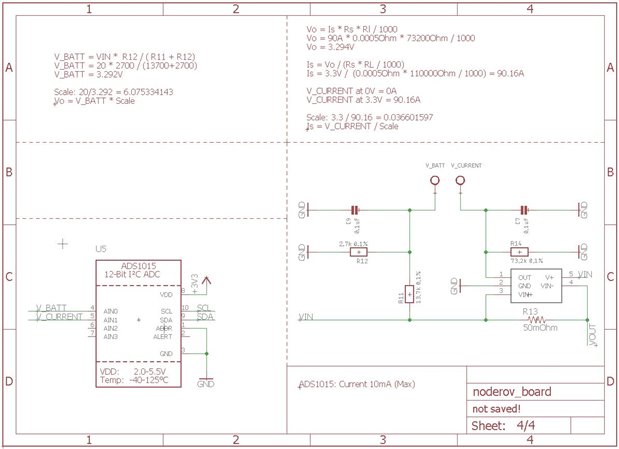
What I am looking for is a circuit which can read amperage and voltage (send to raspberry pi over i2c) of a Lipo and step down 5V and 3.3V for the raspberry PI. Must be able to tolerate up to 4cell LiPo.


I dont really know the efficent way of doing this. My current idea is using two buck converters like the LM2678 one for 5V and one for 3.3V but it seems like a waste of components to create two seperated circuits. Maybe its my only hope?


Also for the current sensing and voltage sensing i see its hard to find examples online. Anyone here got a tip for me? Would the 5v and 3v3 placed after the amp/voltage sensor be a problem?

Any tip is appriciated!


  • Sign in to reply
  • Cancel

Top Replies

  • shabaz
    shabaz over 7 years ago +2 verified
    Hi Thorleif, ti.com/power is your friend, if you click on 'Design Center' there, you can specify that you have multiple loads and the system will offer you various solutions to your requirements. Your…
  • thorleif@tjweb.no
    thorleif@tjweb.no over 7 years ago in reply to shabaz +1
    Hi Shazbaz, thanks a lot for a lot of good information. I've been looking around to sense both current and voltage I can use a INA169, after a little googling i found INA219 which also measures "bus voltage…
  • shabaz
    shabaz over 7 years ago in reply to thorleif@tjweb.no +1
    Hi Thorleif, The INA.. chips can be used for any current range, but are you sure you need it for 90A, this sounds an extremely high level of sustained current at up to 20V. If it isn't sustained then you…
Parents
  • shabaz
    0 shabaz over 7 years ago

    Hi Thorleif,


    ti.com/power is your friend, if you click on 'Design Center' there, you can specify that you have multiple loads and the system will offer you various solutions to your requirements.

    Your parameters will be the range of voltage that you expect to supply, and the output voltages (5V, 3.3V) and maximum current that you wish to support.


    If you're looking to measure current and voltage you can use a multimeter, but if you wish to do this permanently as part of the circuit on your HAT, then it requires an analog-to-digital converter chip with multiple channels, so you can assign two to measure the voltages and two to measure the current consumption, if you wish to measure the 5V and 5.3V outputs separately. If you don't wish to measure them separately then you don't need so many ADC channels. To measure voltage, the voltage (or more likely a scaled value, using a potential divider) is applied to the ADC channel. To measure current, a typical way is to have a low resistance and measure the voltage across it, and then use Ohms Law, i.e. I=V/R. It is known as a current sense resistor, there should be many examples online if you google that term.

    A low-cost ADC is TI ADS111x series, e.g. ADS1115. This is a popular ADC so there will be lots of example source code online.

    • Cancel
    • Vote Up +2 Vote Down
    • Sign in to reply
    • Verify Answer
    • Reject Answer
    • Cancel
  • thorleif@tjweb.no
    0 thorleif@tjweb.no over 7 years ago in reply to shabaz

    Hi Shazbaz, thanks a lot for a lot of good information.

    I've been looking around to sense both current and voltage I can use a INA169, after a little googling i found INA219 which also measures "bus voltage". Which then acts as a voltage, current and power sensor?! It it possible to measure up to 90A 20VDC with this? (Edit: seems like it needs 5v input then I must create 5v first then measure, that means I'll miss the 5v on the measurement. So less accurate readings. So that chip might not work image)

    Here is the circuit using the INA169 i created but I am really insecure about this. Circuit is based on a current sensor I have here from APM.

    image


    Secoundly I have four circuits PCA9685  L3GD20L3GD20 BMP180 LSM303DLHC all connected to reaspberry pi 3.3V how much current can that 3.3V from raspberry give Maybe i dont need two regulators Maybe i can just make a 5v regulator and use the raspberry pi's 3v3

    • Cancel
    • Vote Up +1 Vote Down
    • Sign in to reply
    • Verify Answer
    • Cancel
  • shabaz
    0 shabaz over 7 years ago in reply to thorleif@tjweb.no

    Hi Thorleif,

    The INA.. chips can be used for any current range, but are you sure you need it for 90A, this sounds an extremely high level of sustained current at up to 20V. If it isn't sustained then you'll need to be quick reading the current value, so it depends on your use-case. There isn't enough information to know for sure.

    Regarding what you can run from the 3.3V pin on the Pi, there is no datasheet/specification for the Pi, so try to keep it low (say 20 milliamps max at a guess). The parts you specify do not consume a lot of power, so they should hopefully be alright.

    • Cancel
    • Vote Up +1 Vote Down
    • Sign in to reply
    • Verify Answer
    • Cancel
Reply
  • shabaz
    0 shabaz over 7 years ago in reply to thorleif@tjweb.no

    Hi Thorleif,

    The INA.. chips can be used for any current range, but are you sure you need it for 90A, this sounds an extremely high level of sustained current at up to 20V. If it isn't sustained then you'll need to be quick reading the current value, so it depends on your use-case. There isn't enough information to know for sure.

    Regarding what you can run from the 3.3V pin on the Pi, there is no datasheet/specification for the Pi, so try to keep it low (say 20 milliamps max at a guess). The parts you specify do not consume a lot of power, so they should hopefully be alright.

    • Cancel
    • Vote Up +1 Vote Down
    • Sign in to reply
    • Verify Answer
    • Cancel
Children
  • thorleif@tjweb.no
    0 thorleif@tjweb.no over 7 years ago in reply to shabaz

    Hi again.

    The PCA (PWM driver) says it consumes 25mA pr channel, 16 channels = 400mA so there blows my dream of only needing 5V regulator. image

    90A is "burst", I am making a PCB for kinda a flight controller PCB. Want the chip to be able to handle 12A motors and ESC for 8 motors which is around 96A total. Might be overkill but really want it to be "capable" to handle those bursts. My only consern is powering the PCA with 3v3 will it be enought for ESC to understand the signal when it can only generate 3v3..

    The other chips use sub 10mA in total. I might add a step down for I2C from 5v to 3v3 and run PCA and my ADC on 5V... Thinking loud!

    See latest circuit:


    image

    • Cancel
    • Vote Up +1 Vote Down
    • Sign in to reply
    • Verify Answer
    • Cancel
  • shabaz
    0 shabaz over 7 years ago in reply to thorleif@tjweb.no

    Hi Thorleif,


    The PCA.. device can supply to 25mA per channel (i.e. it is not a consumption figure, but a capability), and it is up to the connected hardware to use however much current as needed up to that value. If each connected device uses just 0.5mA then 16 channels would only use 8mA total for example.

    I don't know what the ESC will consume, if it is not documented then you may need to measure it, to get a ballpark.

    • Cancel
    • Vote Up 0 Vote Down
    • Sign in to reply
    • Verify Answer
    • Reject Answer
    • Cancel
element14 Community

element14 is the first online community specifically for engineers. Connect with your peers and get expert answers to your questions.

  • Members
  • Learn
  • Technologies
  • Challenges & Projects
  • Products
  • Store
  • About Us
  • Feedback & Support
  • FAQs
  • Terms of Use
  • Privacy Policy
  • Legal and Copyright Notices
  • Sitemap
  • Cookies

An Avnet Company © 2025 Premier Farnell Limited. All Rights Reserved.

Premier Farnell Ltd, registered in England and Wales (no 00876412), registered office: Farnell House, Forge Lane, Leeds LS12 2NE.

ICP 备案号 10220084.

Follow element14

  • X
  • Facebook
  • linkedin
  • YouTube