element14 Community
element14 Community
    Register Log In
  • Site
  • Search
  • Log In Register
  • About Us
  • Community Hub
    Community Hub
    • What's New on element14
    • Feedback and Support
    • Benefits of Membership
    • Personal Blogs
    • Members Area
    • Achievement Levels
  • Learn
    Learn
    • Ask an Expert
    • eBooks
    • element14 presents
    • Learning Center
    • Tech Spotlight
    • STEM Academy
    • Webinars, Training and Events
    • Learning Groups
  • Technologies
    Technologies
    • 3D Printing
    • FPGA
    • Industrial Automation
    • Internet of Things
    • Power & Energy
    • Sensors
    • Technology Groups
  • Challenges & Projects
    Challenges & Projects
    • Design Challenges
    • element14 presents Projects
    • Project14
    • Arduino Projects
    • Raspberry Pi Projects
    • Project Groups
  • Products
    Products
    • Arduino
    • Avnet Boards Community
    • Dev Tools
    • Manufacturers
    • Multicomp Pro
    • Product Groups
    • Raspberry Pi
    • RoadTests & Reviews
  • Store
    Store
    • Visit Your Store
    • Choose another store...
      • Europe
      •  Austria (German)
      •  Belgium (Dutch, French)
      •  Bulgaria (Bulgarian)
      •  Czech Republic (Czech)
      •  Denmark (Danish)
      •  Estonia (Estonian)
      •  Finland (Finnish)
      •  France (French)
      •  Germany (German)
      •  Hungary (Hungarian)
      •  Ireland
      •  Israel
      •  Italy (Italian)
      •  Latvia (Latvian)
      •  
      •  Lithuania (Lithuanian)
      •  Netherlands (Dutch)
      •  Norway (Norwegian)
      •  Poland (Polish)
      •  Portugal (Portuguese)
      •  Romania (Romanian)
      •  Russia (Russian)
      •  Slovakia (Slovak)
      •  Slovenia (Slovenian)
      •  Spain (Spanish)
      •  Sweden (Swedish)
      •  Switzerland(German, French)
      •  Turkey (Turkish)
      •  United Kingdom
      • Asia Pacific
      •  Australia
      •  China
      •  Hong Kong
      •  India
      •  Korea (Korean)
      •  Malaysia
      •  New Zealand
      •  Philippines
      •  Singapore
      •  Taiwan
      •  Thailand (Thai)
      • Americas
      •  Brazil (Portuguese)
      •  Canada
      •  Mexico (Spanish)
      •  United States
      Can't find the country/region you're looking for? Visit our export site or find a local distributor.
  • Translate
  • Profile
  • Settings
Test & Tools
  • Technologies
  • More
Test & Tools
Blog Antenna Measurement with the R&S FPC1500 Vector Network Analyzer
  • Blog
  • Forum
  • Documents
  • Files
  • Members
  • Mentions
  • Sub-Groups
  • Tags
  • More
  • Cancel
  • New
Join Test & Tools to participate - click to join for free!
  • Share
  • More
  • Cancel
Group Actions
  • Group RSS
  • More
  • Cancel
Engagement
  • Author Author: shabaz
  • Date Created: 19 Aug 2018 5:56 PM Date Created
  • Views 5702 views
  • Likes 9 likes
  • Comments 19 comments
  • zn-z103
  • return_loss
  • fpc1000
  • swr
  • fpc1500
  • rohde & schwarz fpc1500 spectrum analyzer
  • rohde and schwarz
  • vswr
  • rohde&schwarz
  • antenna
  • rohde & schwarz fpc 1000 spectrum analyzer
Related
Recommended

Antenna Measurement with the R&S FPC1500 Vector Network Analyzer

shabaz
shabaz
19 Aug 2018

Introduction

One really useful use-case for a VNA is to characterise antennas. When radio transmitters operate, the signal travels with virtually no loss over a cable (often a coax cable) and then is radiated by an antenna. But some of the energy may be reflected back towards the transmitter, if there is an imperfect match. The VNA operates in a manner where it can simulate a transmitter, and observe how much of the signal is reflected back. This provides an indication of how well the antenna is performing (the assumption is that anything that isn’t getting reflected back is being mostly transmitted; this isn’t always the case, for instance a 50 ohm resistor will absorb it all, but we assume that a reasonable antenna is attached).


The VNA goes further into the characterisation by also monitoring the phase difference in the reflection versus the input signal. This provides insight into how to modify the antenna side circuitry to better match the transmitter.


I’d recently purchased a low-cost antenna from ebay, and I was curious to see if it really did meet the specifications. This short blog post documents my findings for that antenna, but the steps described here are relevant to any antennas.

image


Connecting it up

The antenna came with an SMA connector. As you can see in the photo above, I used an adaptor to deliberately go from there to an N connector plug, and then attached that to an N socket adaption back down to SMA. There is reason to the madness! For more information, see FPC1500 Spectrum Analyzer - Review but in brief, I wanted the cables that connected the antenna to the VNA to be calibrated out of the measurement. To do that, I needed to make the VNA aware of what constituted the cables, and what constituted the antenna. To define this, I need to pick a reference plane and calibrate the VNA up to that plane. The calibration uses three reference impedances and the tool has three connectors for this. The tool looks like a T-shaped piece with a connector on each end and it is known as an OSL mechanical calibrator – OSL refers to Open, Short and Load. It can also be called an OSL T-piece. The FPC1500FPC1500 supports an electronic calibrator that eliminates a lot of effort and risk of inaccuracy, but I only have the OSL mechanical calibrator, so that is what I used.

image


It just happens that my OSL tool has N connectors (this is very common) so the cable needs to have an N connector too. The photo above shows the approximate location of the calibration plane.


Once the calibration is done, the OSL calibrator tool is removed, and the calibration plane can be attached to the antenna. Since the antenna has an SMA connector, an N-to-SMA adaptor is used. The one in the photo above cannot be removed for the test because it would mess with the calibration plane and the calibration that was just done.


Incidentally, a good quality cable is needed. I used a home-assembled cable that consisted of RG-402 semi-rigid coax (so that things don’t move during the measurements) with SMA connectors soldered to each end and ferrite cores strung on the outside in an attempt to isolate the coax shield from RF, so that it doesn’t influence the antenna much. The antenna ought to be mounted as it would be mounted for a real scenario (i.e. if it would be fitted to an enclosure, then it should be fitted to an enclosure for the measurement too).


Working with VNA Calibration Tools

As mentioned, the easiest way is to use an electronic calibration toolelectronic calibration tool.

Image source: R&S websiteimage


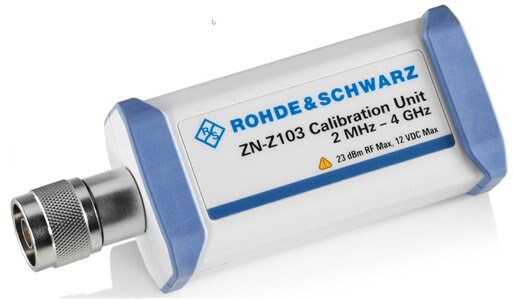
It has a single N plug on one end, and a USB socket on the other. When the USB connector is plugged into the FPC1500, the calibration procedure can be used to electronically switch different reference impedances onto the N connector. Tables of calibration information are also built-in to the tool, so that the FPC1500 is aware of the precise characteristics of the tool’s impedances.


Without the electronic calibrator, an OSL tool can be used. I had to send off mine to be measured, and the returned file specified the parameters that I needed to load into the FPC1500.


The excellent software from Rohde and Schwarz, called InstrumentView, is used for that purpose. It allows me to enter in the information in a user-friendly manner, and it will convert it to a binary file for uploading (e.g. via USB) to the FPC1500.


Here you can see the parameters I entered for my OSL tool:

image


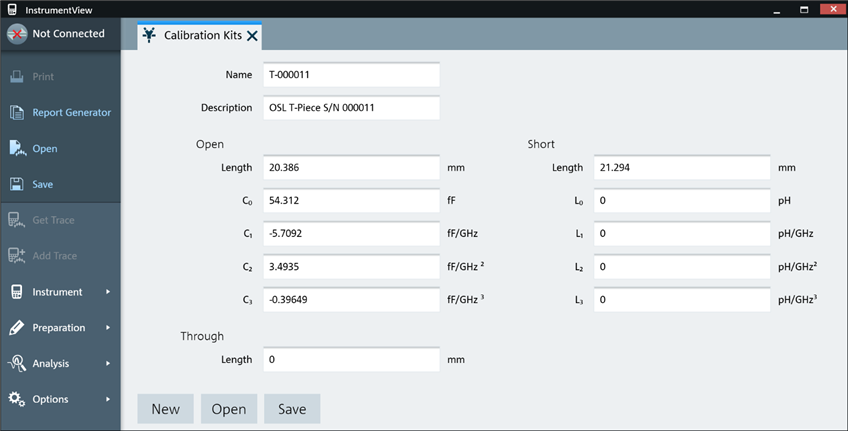
After that I clicked on Save to locally generate and save the binary file, and then went into the Instrument->File Transfer menu to transfer the file to the FPC1500.


Loading the parameters is just the preparatory part of the calibration procedure. Next, the calibration procedure is executed from the FPC1500 menu. It will prompt on the display to attach the OSL tool at the desired reference plane location in three steps, corresponding to the three impedances that the OSL tool offers.


Lots of care is needed during this time, not to disturb any cables, and to double-check that no cables work themselves loose during the procedure.


Once the procedure is done, the OSL tool is disconnected and the antenna can be attached to the VNA!


Results

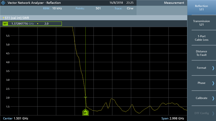
The screenshot below shows the voltage standing wave ratio (SWR or VSWR) of the antenna, across the 0-3GHz range. As can be seen, the SWR falls below 2.0:1 at the marker M1 position which is 1.37GHz. This antenna would therefore function from 1.37GHz to 3GHz and beyond. This is consistent with the ebay advert, which states it works from 1.35GHz to 9.5GHz. I could only test to 3GHz of course. A SWR of 2.0:1 represents a loss of about 10% of power, i.e. 10% was reflected back.


For a lot of the spectrum the ratio was below 1.5:1. At 1.5:1 SWR, the loss is 4%.

image


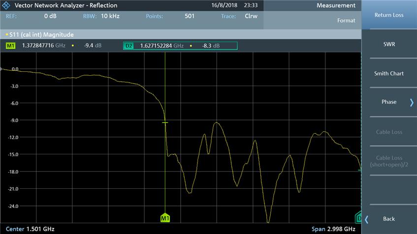
Another way of seeing the same information is to look at ‘return loss’. It shows the same information, just as a different conversion that shows more detail due to the y-axis being logarithmic. The SWR chart has everything cramped in the useful portion. In the return loss chart below, the marker is set to -9.5dB which is a return loss value of 9.5dB, that is equivalent to 2.0:1 SWR.

image


So far the charts have shown scalar information. Now we can go into the vector domain! The swirly diagram here is a Smith Chart. It is discussed in a lot more detail in the FPC1500 review linked to earlier. To cut a long story short, imagine the 0 to 3GHz line in the previous charts, laid out in a different way, which in the case of the screenshot below, happens to begin near the right side of the circular chart, spirals downward and inward, and finally ends up at somewhere else (near the center of the chart in this example).


Anything near the center of the chart corresponds to the antenna looking like a 50 ohm resistance at that frequency, and the loss would therefore be very low. Anthing far away from the center corresponds to an impedance that is not close to 50 ohms resistance. The green marker M1 corresponds to the 1.37GHz position on the swirly yellow line, and it is close to the center. The D2 marker is at a delta of 1.63GHz to M1, i.e. it is at 3GHz absolute frequency, and it too is close to the center.

image


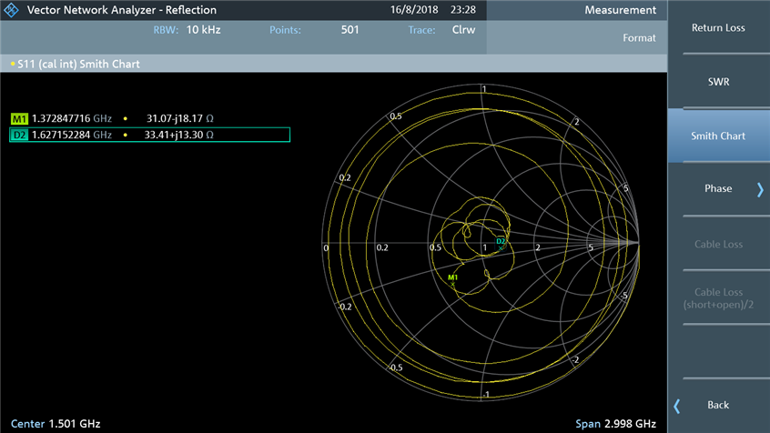
The Smith Chart view is helpful because it graphically describes what needs to be done to the circuit in order to make the match closer to the center, for any desired portion of the spectrum. This too is discussed in more detail in the FPC1500 review.


Summary

It was easy to use the FPC1500 to verify an antenna. The procedure is just a few button-clicks once the calibration procedure is done. The electronic calibration tool would reduce the calibration steps and make that part of the procedure more reliable, but it is perfectly feasible to do it using manual tools too.


The VNA provides valuable information on how to tune an antenna using components. The scalar charts provide a good summary of the overall match across the desired frequency range.

  • Sign in to reply

Top Comments

  • jc2048
    jc2048 over 7 years ago +3
    This is really good - thanks for posting it. The readings for the second marker are RELATIVE to the first, aren't they? I was a bit puzzled by the low resistance given the placement of the marker but,…
  • mcb1
    mcb1 over 7 years ago in reply to shabaz +3
    Sadly I missed learning about valves/tubes although I'm still keen to learn. Valves glow when the filament is working ... They get warm, and we found that the Taxi channel transmitter provided a very good…
  • shabaz
    shabaz over 7 years ago in reply to jc2048 +3
    Hi Jon, Thanks for reading! It's great to hear about your experiences with these antennas. I've not done any EMC tests so log-periodics are new to me, I was looking for a directional wideband antenna,…
Parents
  • jc2048
    jc2048 over 7 years ago

    This is really good - thanks for posting it.


    The readings for the second marker are RELATIVE to the first, aren't they? I was a bit puzzled by the low resistance given the placement of the marker but, if I'm now understanding it correctly, it's actually at about 64 ohms (real part) ie the sum of the two.


    That aerial is a log-periodic, isn't it. They're used a lot for (higher frequency) emc work because of the very wide bandwidth. I've often wondered what the actual response would look like. We had one with larger dimensions (not a pcb, obviously, but physical rods) for the range 300MHz to 1GHz (below 300MHz we used a bi-conical).  It's surprisingly good given that the vast width of the response is coming from the separate elements being summed together - I would certainly have expected it to be a bit up and down, because of the tendency for the elements to interact (they kind of act like the reflectors/directors of a Yagi to each other in a very complex way - how in earth you design one I don't understand - perhaps you start at the low frequency end and optimise as best you can as you work your way along adding the elements), but would have expected it to be more extreme than this. For emc use it was fine because it was characterised with the test receiver to give a level overall response for the measurements.


    I've never been too clear how directional it is - back then we treated it like a Yagi (ie just pointed it directly at the EUT) but maybe that isn't the case.


    I don't know a lot about rf, but I wouldn't have thought it would be too good for a transmitting aerial because of that drop down close to 25 ohms (it wouldn't necessarily be very comfortable for a power amplifier designed for 50 ohms to drive that), but then where would you want to use a wideband aerial for transmitting (other than, maybe, in a test situation).

    • Cancel
    • Vote Up +3 Vote Down
    • Sign in to reply
    • More
    • Cancel
Comment
  • jc2048
    jc2048 over 7 years ago

    This is really good - thanks for posting it.


    The readings for the second marker are RELATIVE to the first, aren't they? I was a bit puzzled by the low resistance given the placement of the marker but, if I'm now understanding it correctly, it's actually at about 64 ohms (real part) ie the sum of the two.


    That aerial is a log-periodic, isn't it. They're used a lot for (higher frequency) emc work because of the very wide bandwidth. I've often wondered what the actual response would look like. We had one with larger dimensions (not a pcb, obviously, but physical rods) for the range 300MHz to 1GHz (below 300MHz we used a bi-conical).  It's surprisingly good given that the vast width of the response is coming from the separate elements being summed together - I would certainly have expected it to be a bit up and down, because of the tendency for the elements to interact (they kind of act like the reflectors/directors of a Yagi to each other in a very complex way - how in earth you design one I don't understand - perhaps you start at the low frequency end and optimise as best you can as you work your way along adding the elements), but would have expected it to be more extreme than this. For emc use it was fine because it was characterised with the test receiver to give a level overall response for the measurements.


    I've never been too clear how directional it is - back then we treated it like a Yagi (ie just pointed it directly at the EUT) but maybe that isn't the case.


    I don't know a lot about rf, but I wouldn't have thought it would be too good for a transmitting aerial because of that drop down close to 25 ohms (it wouldn't necessarily be very comfortable for a power amplifier designed for 50 ohms to drive that), but then where would you want to use a wideband aerial for transmitting (other than, maybe, in a test situation).

    • Cancel
    • Vote Up +3 Vote Down
    • Sign in to reply
    • More
    • Cancel
Children
  • shabaz
    shabaz over 7 years ago in reply to jc2048

    Hi Jon,


    Thanks for reading! It's great to hear about your experiences with these antennas.

    I've not done any EMC tests so log-periodics are new to me, I was looking for a directional wideband antenna, and ended up reading about it.


    Sorry yes, that's a delta, I ought to have switched the display to absolute, but I'd already grabbed the screenshot and powered off by the time I noticed. It defaults to a delta marker for the all subsequent markers, unless I explicitly set it to absolute marker mode. You're right, it's about 64 ohms real part.


    I was sceptical that a sub-£10 log-periodic could function well, but all looks great so far. I forgot to add the link to the antenna: https://www.ebay.co.uk/itm/1PCS-new-UWB-Ultra-Wideband-Log-Periodic-Antenna-1-35-9-5GHz-15W-High-Accuracy-/322920854250?…

    They've got the phase reversal implemented with each element by having the even and odd elements on other sides of the PCB, which was a great idea.

    The reason I got it was exactly that, to explore it, and to examine and learn the physical construction method, so that I could try to make one for a different frequency range, from about 800MHz upward.

    Regarding design, there are some software programs to calculate the element lengths etc., so I may try my hand at that, to see how it goes. I guess the experts would take the calculations to the next step and simulate, but that's unknown territory for me : ( The fancy software packages cost too much, but even with the free packages, they need knowledge or experience that I don't have. But at least I can measure the failures image


    I'm going to use this web link for the calculations - the whole website a fantastic resource for RF: https://www.changpuak.ch/electronics/lpda.php


    In transmit operation I don't intend to operate with much power, just a tiny bit with the VNA output port being the transmitter, or an SDR without any amplifier attached, to learn a bit about it, and for one or two experiments.

    According to that, a design covering from 800MHz to at least 3GHz is possible in a space of about 200x200mm, which is still in affordable PCB range (if I end up doing it as a PCB too). That would be a handy antenna to have for experiments, allowing for use in the license-free sub-1GHz range too, and at frequencies where cheap SDRs can be used as receivers.

    I can imagine the 300MHz antenna cost a fair bit : )

    • Cancel
    • Vote Up +3 Vote Down
    • Sign in to reply
    • More
    • Cancel
  • jc2048
    jc2048 over 7 years ago in reply to shabaz

    I was sceptical that a sub-£10 log-periodic could function well, but all looks great so far.

    It seems like a good way to get precise elements exactly where they need to be. The thinness of the elements doesn't matter at the kind of power levels you're working at - rf currents at these frequencies run very near the surface, so the 35u copper thickness isn't an issue. Structurally, it might be a problem with a larger aerial. Fibreglass does have a tendency to warp, though in this case the pattern on both sides matches fairly well, so at least that isn't pulling it to one side (you could use wooden battens if you needed to stiffen up a larger aerial).


    I'm going to use this web link for the calculations -

    I can see one problem with that. The fibreglass/resin has a dielectric constant higher than air and that will change the element lengths because it modifies the wave velocity (same effect as the ceramic in a chip antenna, only less so). There's also the problem of


    a) knowing what the dk actually is (pcb datasheets traditionally specify it at low frequency [a few megahertz], but it varies with frequency), though having said that there should be a lot of info now on how FR4-equivalent behaves at 2.4GHz.


    b) dealing with the fact that it changes with frequency with an aerial spanning a wide range


    Still, the good thing about pcbs is that they are fairly cheap and lend themselves to experimentation and you've now got a very nice piece of test equipment to do it with.


    I don't know how much the aerial cost. It was purchased back in the early 1990s when the EMC legislation was first coming in and was a complete package - the two aerials, a scanning receiver and a LISN. It came from an Italian company. I wasn't involved in buying it and didn't get to actually use it (the technical director did that side of things, but there was a lot of interaction between us because I was doing design). As I understand it, at the time it was much less money than a suitable spectrum analyser with the performance needed. I only got to use it much later. The aerials themselves were essentially hand built. Each element was a rod that was drilled and tapped at one end. The support bar was drilled and tapped too and there was a short length of threaded rod to join the two. They could be disassembled for storage or transport but in such a way as to allow for quick and precise reassembly. There was also a beautiful stand, made of turned hardwood nicely polished, to support the aerial at the required height, with the fittings being non-metallic (hard white plastic - maybe machined ptfe?). In contrast, the table to support the EUT was made by one our technicians and wasn't quite as elegant and refined, though it did the job.


    I do remember that one time the technical director went to the test house they suggested that he put a bunch of ferrites either end of the cable to stop rf running along the outside of the shield, in the same way as you're doing here.

    • Cancel
    • Vote Up +1 Vote Down
    • Sign in to reply
    • More
    • Cancel
element14 Community

element14 is the first online community specifically for engineers. Connect with your peers and get expert answers to your questions.

  • Members
  • Learn
  • Technologies
  • Challenges & Projects
  • Products
  • Store
  • About Us
  • Feedback & Support
  • FAQs
  • Terms of Use
  • Privacy Policy
  • Legal and Copyright Notices
  • Sitemap
  • Cookies

An Avnet Company © 2025 Premier Farnell Limited. All Rights Reserved.

Premier Farnell Ltd, registered in England and Wales (no 00876412), registered office: Farnell House, Forge Lane, Leeds LS12 2NE.

ICP 备案号 10220084.

Follow element14

  • X
  • Facebook
  • linkedin
  • YouTube