


Note: This project, by its nature, needs to connect to the mains supply. It shouldn’t be left unattended and should only be constructed and used by engineers. The information is for educational purposes only, and there is no guarantee that it will be safe, even if it is constructed exactly as specified here.
It is believed to be safe when connected correctly, and when used in a lab, but as mentioned there is no guarantee and no liability. Furthermore, this project is not intended for home use because any child could poke a metal implement into the connections and receive an electric shock.
Introduction
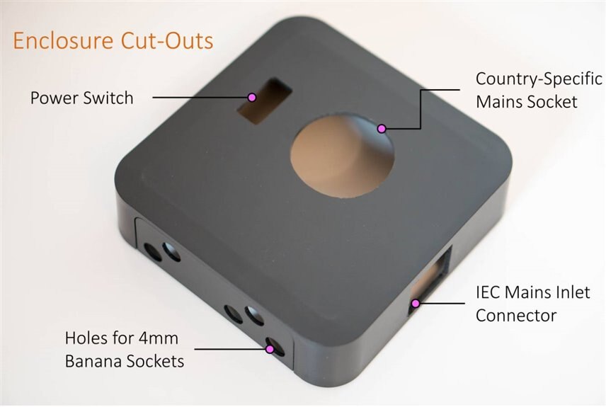
I needed to build up a small box intended for power measurement. It primarily consists of an IEC mains connector, a mains socket, and a few 4mm banana socket connections. It doesn’t do much on its own, but combine it with either a mains clamp meter or analyzer, or multimeter or oscilloscope (with appropriate isolated probes, not normal ‘scope probes!) then it can be highly useful. It can be used to observe current consumption (perhaps by using an external current sensor) or for measuring power by analyzing the current consumption and the voltage phase. This is great for finding out how much power appliances use.
The project here uses a UK mains socket for the appliance-under-test, but it could be swapped out with the appropriate socket for the country of interest, for making this project work in a different country.

Why is a Breakout Box Needed?
A lot of test equipment uses connectors like banana sockets, but the home mains supply has very different connections. It is useful to have a box to convert between the two systems, to provide the appropriate connections for attaching test gear. Precautions are still required because all the connections have potentially lethal voltages, so the breakout box is a specialist bit of equipment that must not be left around if non-experts/kids are nearby, even if the equipment is fully unplugged. It should be locked in a drawer when not in use.

Breakout boxes are also available commercially, but they are quite expensive (of the order of several hundred $). Building a custom breakout box saves a bit of money in exchange for time spent making it, but also provides the opportunity to add some extra functionality too. In my case, I decided to add a (very large) mains filtermains filter, which I think is quite useful to make life easier for any measurements. It will remove a lot of high-frequency content (the home mains supply has a lot of junk!).
With this breakout box, I can monitor the current consumption, and the power usage of connected appliances, using clamp meters or power analyzer meters. I have a clamp meter, and also a power meter which I intend to use with this breakout box. I also have a mains power monitor (it reduces and isolates the voltage such that an oscilloscope can be connected) which could also be used with the breakout box, to see what junk is emitted from the equipment-under-test. I can also temporarily attach equipment to the mains supply without wiring up a mains plug, by using the banana plugs; this is handy when quickly testing a mains operated circuit. So, there are lots of uses for such a breakout box. It would be great to hear about what modifications people would do, to extract more usefulness out of this project. One idea I had was to build in a cheap power meter too so that the box could be used standalone without any additional test equipment too. Anyway, it’s just an idea for future consideration, and it might need a bigger box!
Circuit Overview
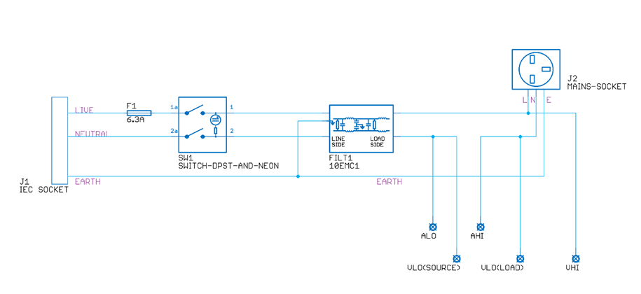
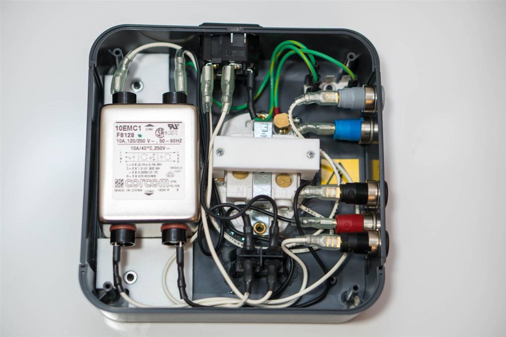
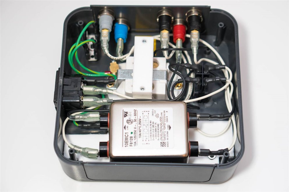
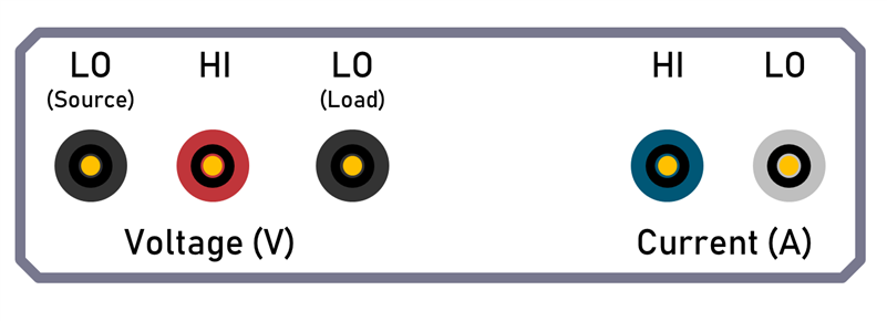
The circuit is straightforward; the incoming mains supply passes through a fuse and then connects to the double-pole mains switch that connects to the mains filter input. The output of the mains filter is connected to the mains socket for the equipment-under-test, but with a break where two banana plug sockets (titled ALO and AHI) are attached, for series connection of the current measuring apparatus, such as a current shunt. If a clamp meter is being used then these two connections would be shorted with a banana lead, and the clamp meter would be connected around the lead. Three additional banana plug sockets are wired for measuring the voltage applied to the equipment-under-test. There are three connections because sometimes it is preferable to measure before the current shunt, and sometimes it is preferable to measure after the current shunt.
Creating the Enclosure
A Takachi enclosureTakachi enclosure was used, and holes were drilled for the various connections.
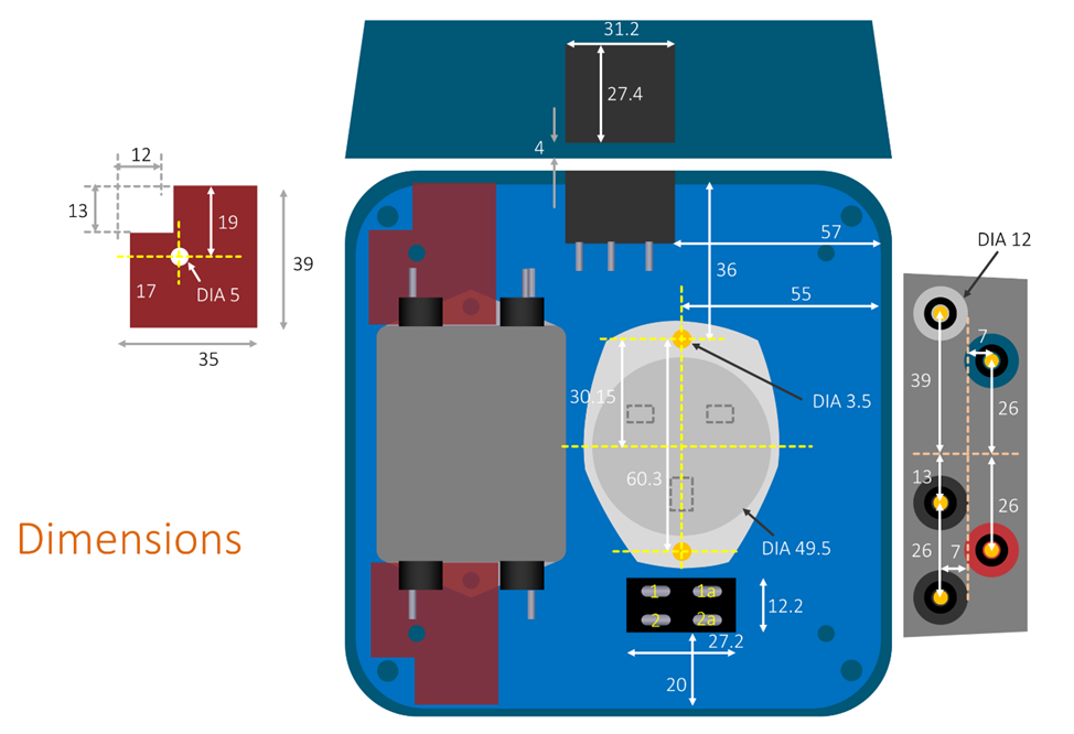
The required dimensions are shown here (it isn't a true CAD drawing but it is self-explanatory); the shapes on the left indicated in red are used to secure the mains filter in place (see the later photographs):
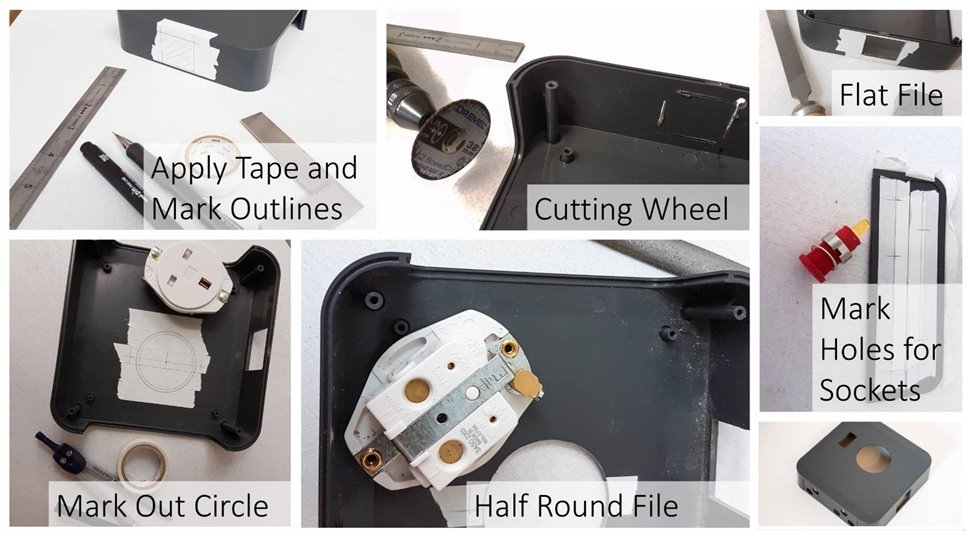
See the photo below for a quick walkthrough of the marking/cutting/filing process. I like marking on tape, to keep the enclosure clean. A Dremel cut-off wheel was used for the larger rectangular holes, and then the corners were drilled out and then filed. For the circular hole, lots of smaller holes were made, and then the cut-out was made circular by using a half-round file. It doesn’t take long because the plastic is soft.
The UK mains socketUK mains socket posed a bit of a problem because it had screw holes for mounting on the surface. I didn’t want them there for cosmetic reasons, so instead I created a bracket of the correct height to keep the socket tightly sandwiched between the top and bottom surfaces of the enclosure once the enclosure is screwed together. Also, epoxy glue was used so that the load would be shared between the top and bottom surface when a mains plug was inserted. The bracket needed to be made from flame retardant plastic; I used PTFE because it is easy to cut. All this is optional; it is unnecessary if you’re ok with the screw holes on the top surface.
The IEC mains inlet connectorIEC mains inlet connector is intended for slightly thinner walled enclosures, so I needed to thin the wall in a small area so that the connector clicks into place.
To hold the filter in place, a couple of brackets were made, again from PTFE sheet. Aluminium sheet could be used too, I just didn’t have any handy. The brackets are optional and not needed if you’re prepared to have screws on the top surface of the enclosure.
Wiring
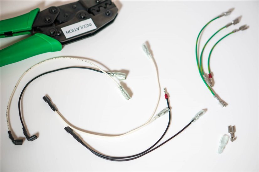
I used 16AWG white wirewhite wire, black wireblack wire and green-yellow wiregreen-yellow wire. For the connections, I used crimp terminals (mainly 16AWG terminals16AWG terminals, but also some 13AWG terminals13AWG terminals where two wires needed to be inserted) and boots or heat-shrink tubing. I used a Duratool crimp toolDuratool crimp tool which produces really excellent results but requires quite a lot of force. It secures the wire and the insulator with a single action. In the photo below, the side of the tool marked ‘INSULATION’ is the side where the wire is fed in. The other side is where the crimp terminal is held.
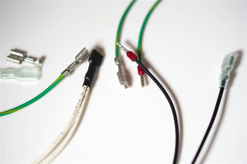
The switch with integrated lampswitch with integrated lamp requires right-angle crimp terminals which I didn’t have, so I folded them over manually. Not great, but I may swap them out later. For the UK mains socket there are screw terminals, so ferrules were used to make sure that all strands made good contact. I used a Knipex toolKnipex tool for the ferrules (see here for a review and ferrule part codes).
There is a fair amount of cabling but it was fairly quick to cut and crimp them all.
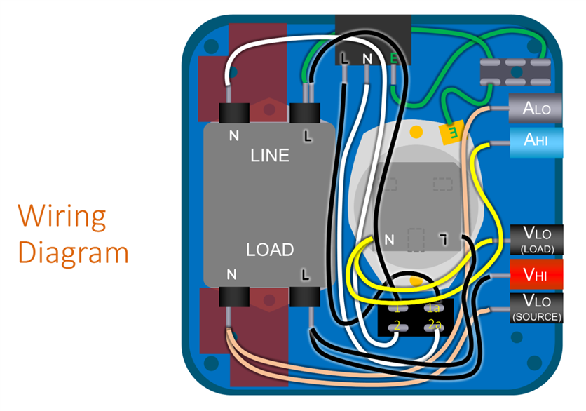
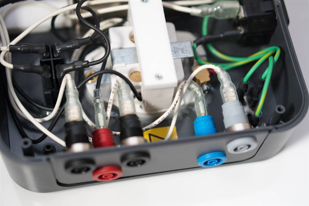
I used white wires for neutral connections and black for live connections. In the diagram below, the green wires are earth connections, the black lines indicate live connections, and the remaining wires are all neutral (just represented in various colors for clarity). Hirschmann banana sockets were used; a blue socketblue socket, two black socketsblack sockets, a grey socketgrey socket and a red socketred socket.
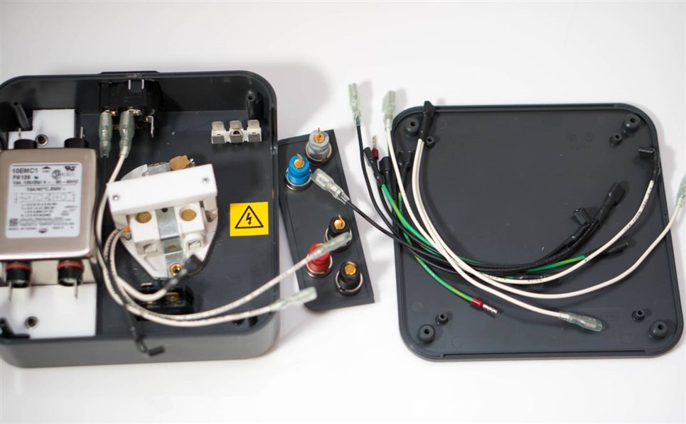
Finally, it was complete! I used some 5-minute epoxy resin glue to secure the mains socket and the switch although it wasn’t really necessary.
Prior to fitting the wires, I applied a tiny dab of epoxy resin glue to the retaining collar/nut around the banana plug sockets, so that they wouldn’t loosen over time. I also stuck a mains warning label inside (the outside of the enclosure will require a lot of warnings and labels too).
In summary, everything fitted really well. The enclosure base was screwed on. It comes with rubber feet too. All that remains is to perform some tests and apply some instruction and warning labels to the enclosure.
Testing It
Prior to closing up the box, I gave it an inspection and made sure all connections felt secure. Next, prior to connecting to a real mains supply, a couple of IEC mains cables were connected to the box, to the IEC socket and the UK mains socket. This allowed me to stick multimeter test probes into the leads and test out the connections without connecting to any mains supply. I confirmed that the live, neutral, and earth connections were not shorted at either end, and then confirmed that the live and neutral connections were end-to-end when the switch was turned on, and a test lead was used to short the AHI and ALO connections. I also tested with the connections opened, and with the switch turned off, to check the expected behaviour.
Finally, I attached the mains supply and checked with a multimeter that 240VAC was measurable across the VHI and VLO connections and that it was possible to measure current for a connected load, by using a current clamp meter placed around a test lead that was shorting the AHI and ALO connections.
Labels
The following labels were printed out and covered with sticky plastic (I used wide transparent packaging tape) and then stuck down to the box.
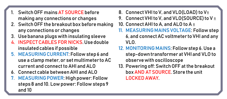
The following procedures label was intended to remind me to always follow a procedure when using it. So, for instance, to measure the mains voltage, I would start at the beginning, and follow steps 1-4, since they are common to all of the procedures, and then skip to the blue highlighted step 11, which tells me to follow step 6, and then connect a voltmeter to two connections. Anything in red is extremely important (everything is important). Please note, these steps may have errors or may not follow best practices or legislation. It is presented in good faith to show what I did, but no liability can be accepted. If you have modifications, please do share them in the comments so everyone can learn from them.
Summary and Next Steps
I’m happy that it was possible to build a mains test box with the features I wanted, at low cost, with just a weekend’s effort. It will be really useful for me to be able to check mains device current consumption.
It might also be worthwhile to drill out one more hole for a banana socket for an earth connection, since I have space for that. It would come in handy when temporarily connecting a mains circuit via the banana plugs.
With hindsight, I might have picked a larger box, in order to have made it easier to cable up and to have space for adding more features.
Thanks for reading!
Top Comments
-

mcb1
-
Cancel
-
Vote Up
+4
Vote Down
-
-
Sign in to reply
-
More
-
Cancel
-

shabaz
in reply to mcb1
-
Cancel
-
Vote Up
+5
Vote Down
-
-
Sign in to reply
-
More
-
Cancel
Comment-

shabaz
in reply to mcb1
-
Cancel
-
Vote Up
+5
Vote Down
-
-
Sign in to reply
-
More
-
Cancel
Children