


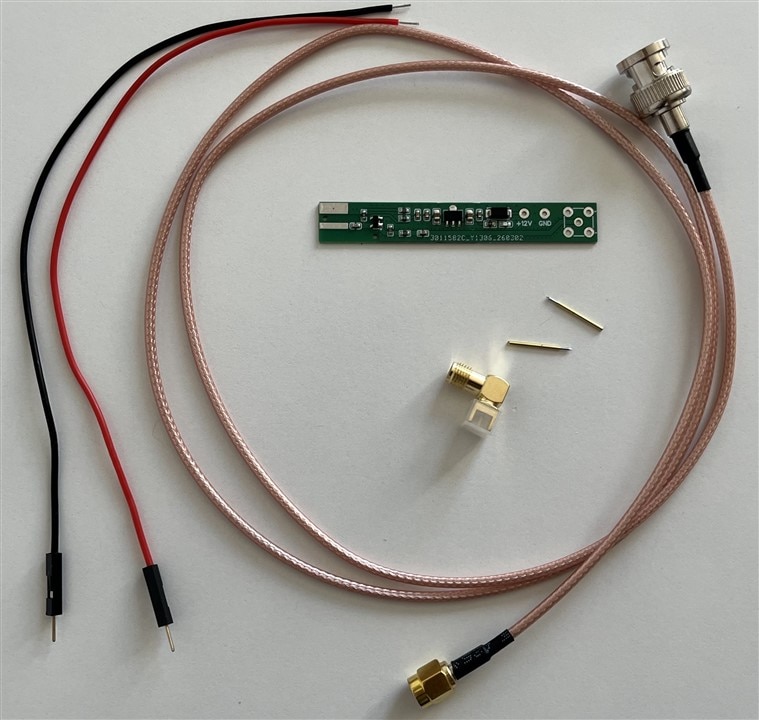
During the last test of the Si5351 clock generator, I thought that it would be nice to compare measurement results between a passive probe to an active probe. I have found one based on a well-known design with usage of the high frequency BF998 FET transistor input stage. It is really cheap as for an active oscilloscope probe, and based on opinions on the network, it performs really well, especially up to the 500 MHz, which is the limit of my scope. I have bought one on eBay. The probe came with a SMA to BNC cable, SMA connector and 2pcs of golden-plated spring-loaded pins. This oscilloscope active probe has the following parameters:
- 100kHz - 1.5GHz bandwidth
- input capacitance 0.5pF
- input impedance 10Mohm
- gain -15dB +/-2.5dB (fits approx. 5:1 the probe voltage ratio)
- DC supply voltage 7V - 30V
-
reverse supply voltage protection
After soldering the pins, SMA connector and power supply wires, I was ready for a measurement of the clock from the output of the Si5351 generator.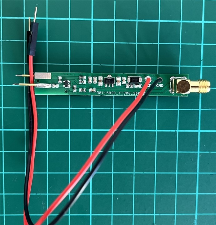
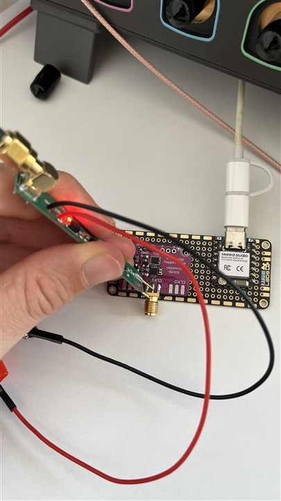
I have powered a probe at 12 V and changed the oscilloscope input to 50 Ohm. Here are the results of measurements for different frequencies:
| {gallery}Measurements |
|---|
|
10 MHz clock |
|
20 MHz clock |
|
50 MHz clock |
|
100 MHz clock |
|
150 MHz clock |
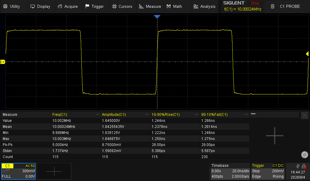
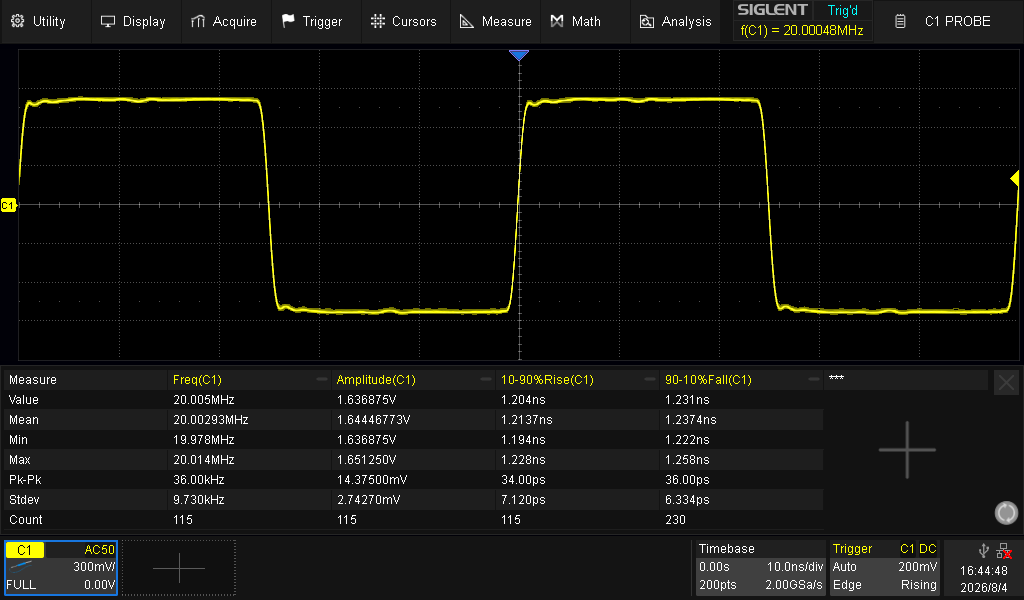
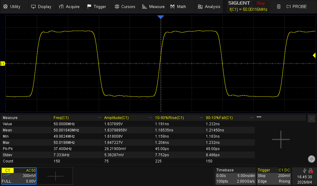
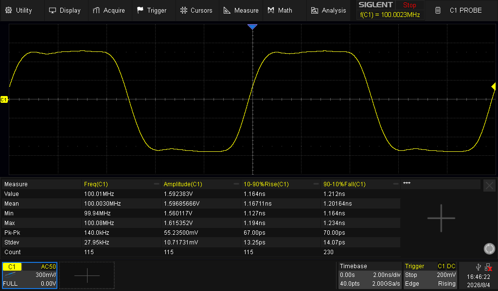
There is real improvement in the quality of the measured signal. Here is a comparison of the measured 150 MHz signal with the SPL5050A passive probe, which has a bigger capacitance: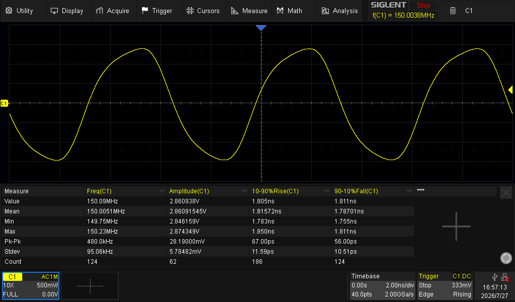
to the same signal measured with active probe:
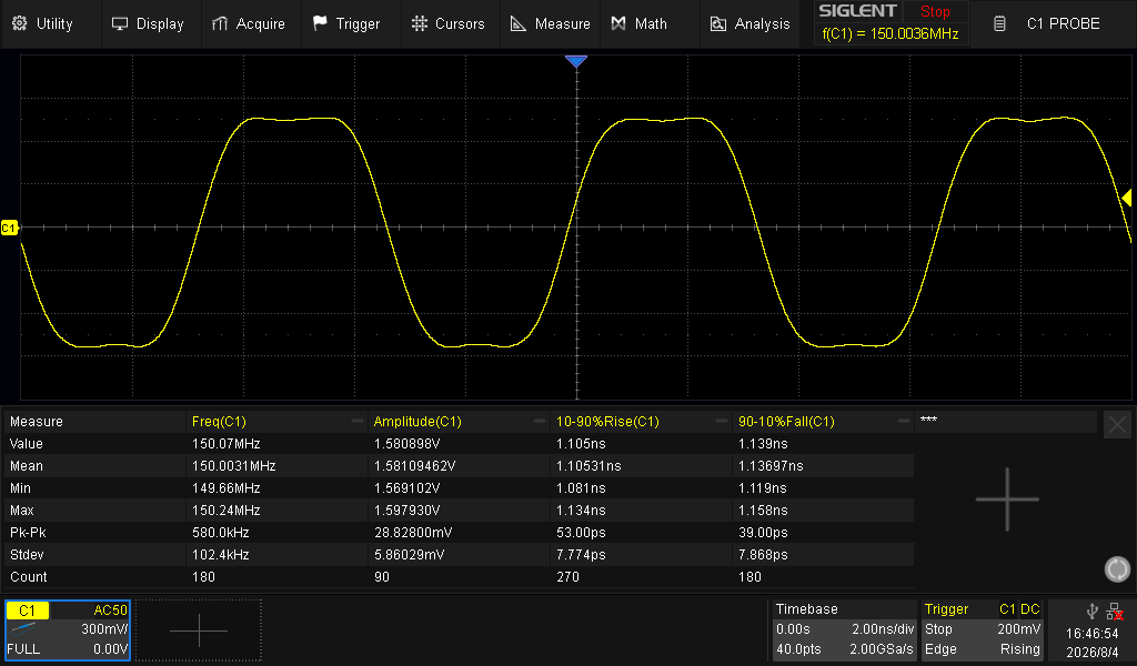
Probably a similar improvement in that case could be achieved with the Z0 probe (low-impedance probe), when the high impedance of the probe is not required (e.g. for digital signals).
This active probe meets my expectations. I need to think about a case for it and maybe change the power supply to a battery.
Update 08.08.2026
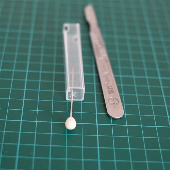
I have found that a container for the iron tip will really fit the PCB with an active probe. The only things that required modification were to perform holes with proper free space for spring-loaded pins and enlarge holes for power supply wires. The holes for spring-loaded pins I performed with a thick needle. The holes for power supply wires were cut with wire cutters and finished with a scalpel. After inserting the PCB with an active probe, everything fitted very well. Below there are photos with the result of this modification:
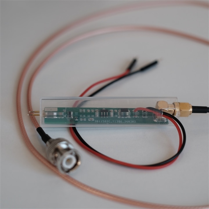
Now it is much easier to operate or hold it.
