


Introduction
This blog post discusses a project to build a simple logic analyzer (hobby-grade; it samples at up to 24 Msps, good enough for basic debugging when other tools are not available), but it has a few extra features too. This project could be handy for troubleshooting I2C or SPI when working on projects. It can in theory also be used for generating protocol output too, and for operation as a programmer for microcontrollers and FPGAs.
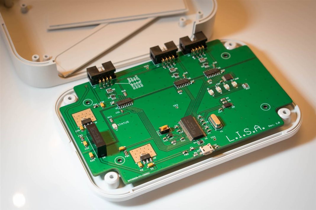
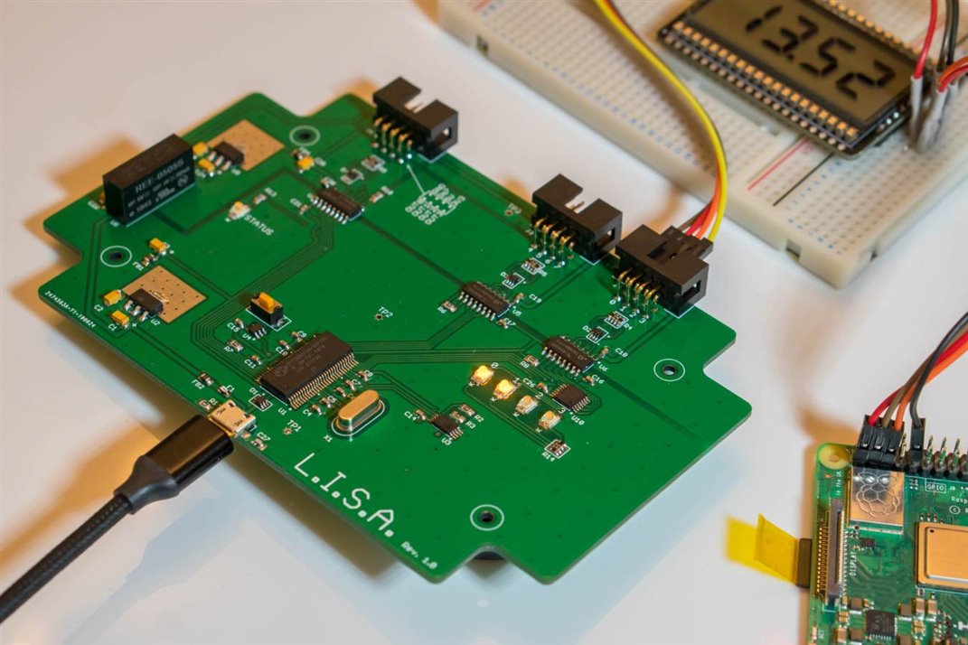
Nearly all digital electronics nowadays has a number of serial busses, either connected between subsystems inside the equipment, or exposed to the outside world. When troubleshooting such electronics, or even when prototyping, occasionally there is a need to attach to these interfaces and either monitor or inject information. These serial interfaces operate at a low-level, i.e. operating at the bits and bytes level and below! Enter the Low-Level Interface and Subsystem Analyzer, L.I.S.A.
It has dual-in-line (DIL) headers for attaching to (say) jumper wires or ribbon cables, to the equipment under test. The other end connects to a PC or Pi via USB. The project is designed to fit into an enclosure, but I have not got around to doing that yet.
Cypress FX2LP
Due to short time to design this project (schematic and PCB layout were completed in one day), I used Cypress Semiconductor’s FX2LP technology because it simplifies high-speed data transfer via USB. FX2LP chips contain a very basic microcontroller, but includes a USB accelerator function that bypasses the processor and allows for data to be shuttled between input/output pins on the chip, and the USB attached host, extremely rapidly. The FX2LP chips work at USB 2.0 High Speed (480Mbit/sec) rates.
(Image source: Cypress website)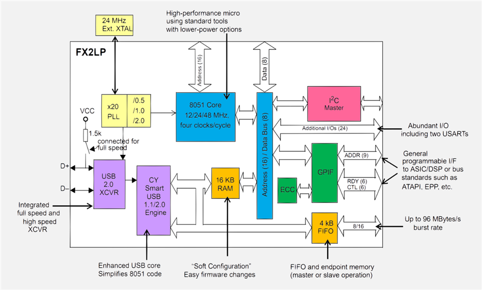
There are also FX3 chips which operate at an incredible 5Gbit/sec (USB 3.0), and I’d like to explore them one day.
Such a design requires the actual protocol decoding to be done on the connected computer. I liked the idea of having some basic, general-purpose hardware that could be attached to any PC, and have the bulk of the processing done on the PC. It should also work with a Pi, for portable, battery-powered use and possibly long-term logging too.
Incidentally, the commercial Saleae logic analyzer uses the same FX2LP chip (I do not own this device, but there are photos of the internals on the web). The Saleae device contains the FX2LP chip and little else. Anyway, it is likely compatible, if the firmware is available. I’m personally more interested in creating new firmware eventually, with the extra features mentioned above. Today, with no firmware or software written for it, it is nevertheless supported by the open source Sigrok/PulseView project, with no extra work, because many logic analyzers use the same chip.
Design Overview
The diagram below shows the functionality on the board. It contains a total of 8 input ports, and 4 output ports. LISA version 1.0 supports 3.3V logic levels only, although it will tolerate 5V on the inputs. Isolated 5V and 3.3V supplies are exposed on a connector, so that LISA can power up some externally attached equipment if necessary.
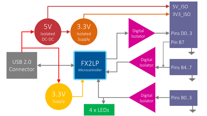
Everything on the board is hand-solderable with an iron (no need for reflow tools), so this should be an easy project to construct with the minimum of tools.
The project is expandable too; instead of using right-angle header pins, it is possible to use vertical pins, and plug on a board on top, which could (say) expose input/output at different logic levels such as RS232.
Example Uses
Here are some example use-cases that are envisaged:
- Troubleshooting/sniffing I2C, SPI and UART
- Long-term logging/monitoring of I2C, SPI and UART
- Generating I2C, SPI and UART traffic
- FPGA programmer (JTAG)
- ARM programmer (SWD)
- Simple Logic Analyzer (8 port)
- Controlling external equipment (4 outputs) with a future relay card
- Logging/monitoring analog signals with a future ADC card
- Powering external circuitry with the 3.3V or 5V outputs
Building It
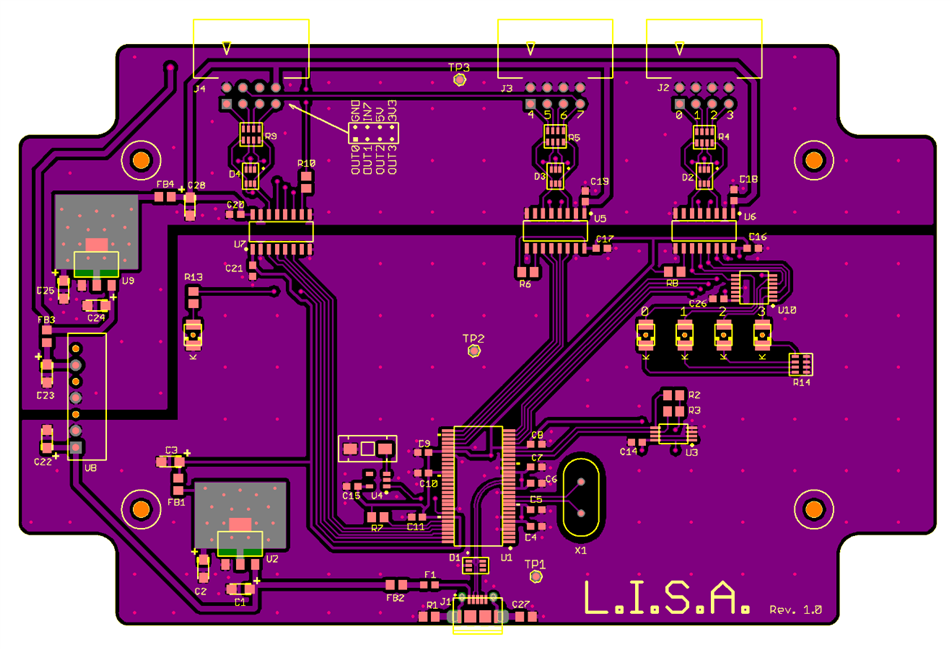
The PCB files are attached to this blog post, ready to be sent to a PCB factory. It is a 2-layer board, 142x90mm. Everything can be hand-soldered with a small-tipped (around 1mm) soldering iron.
A few of the parts need some thought due to the size of them. For the micro USB connector, I put a small dab of solder paste on the pads, and then placed the connector on the board, and then heated the pins. It’s quite easy. I used solder paste in a similar way for the LEDs. Everything else was soldered as usual with thin (0.274mm) solder wire.
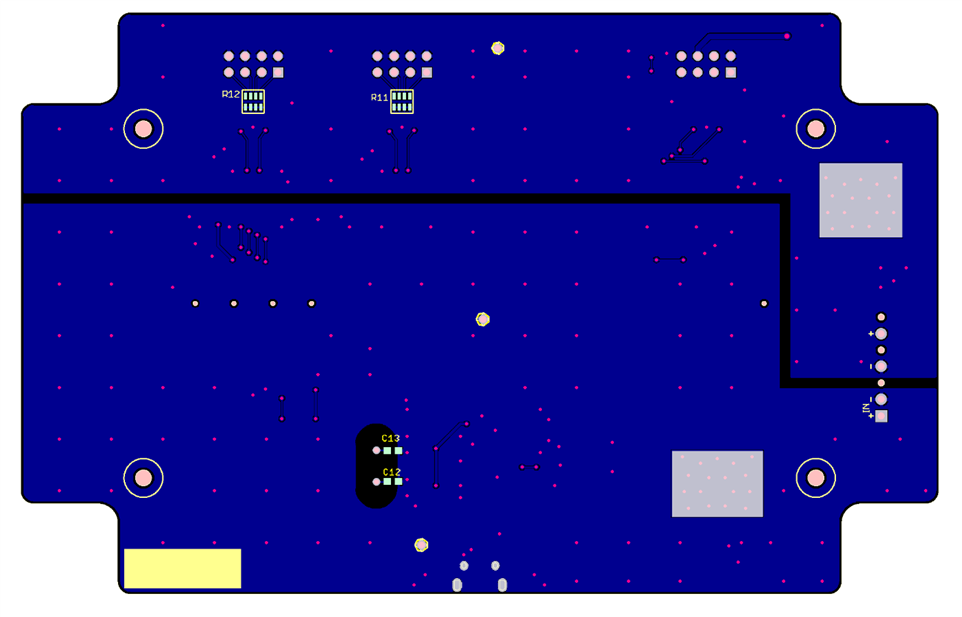
The diagrams here can be used for locating the components on the board.
Board underside:
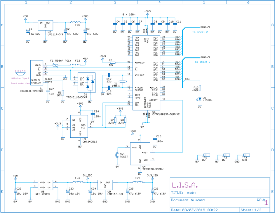
Here is the schematic (click to enlarge), sheet 1 of 2:
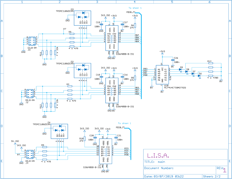
Sheet 2 of 2:
Parts List
| Product Name | Manufacturer | Quantity | Buy KitBuy Kit |
|---|---|---|---|
| Laird HZ0805E601R-10HZ0805E601R-10 Ferrite bead, approx 0805 size | 4 | Buy NowBuy Now | |
| 100n 0603 CAPACITOR | 17 | Buy NowBuy Now | |
| 10M R0805 RESISTOR | 1 | Buy NowBuy Now | |
| 10k 0805 RESISTOR | 1 | Buy NowBuy Now | |
| 10n 0805 CAPACITOR | 1 | Buy NowBuy Now | |
| 10u 10V Tant A Capacitor TPSA106K010R1800 | 4 | Buy NowBuy Now | |
| 12p 0603 CAPACITOR | 2 | Buy NowBuy Now | |
| 2.7k 0805 RESISTOR | 2 | Buy NowBuy Now | |
| 24MHz CRYSTAL HC49U 12pF | 1 | Buy NowBuy Now | |
| 27k 0805 RESISTOR | 3 | Buy NowBuy Now | |
| 33k Quad Resistor Array | 2 | Buy NowBuy Now | |
| 470R Quad Resistor Array | 1 | Buy NowBuy Now | |
| 47R Quad Resistor Array | 3 | Buy NowBuy Now | |
| 470R 0805 RESISTOR | 1 | Buy NowBuy Now | |
| 47u 6.3V Tant A Capacitor TPSA476K006R0800 | 4 | Buy NowBuy Now | |
| 500mA POLYFUSE 0603 MF-FSMF050X-2 | 1 | Buy NowBuy Now | |
| CAT24C512YI-GT3CAT24C512YI-GT3 EEPROM, I2C, 512kbit | 1 | Buy NowBuy Now | |
| CY7C68013A-56PVXCCY7C68013A-56PVXC Microcontroller FX2LP | 1 | Buy NowBuy Now | |
| DIL8 Header R/A T821108A1R100CEUT821108A1R100CEU | 3 | Buy NowBuy Now | |
| LED Yellow KPD-3224SYCKKPD-3224SYCK | 5 | Buy NowBuy Now | |
| LD1117S33TR 3.3V 800mA Linear Regulator | 2 | Buy NowBuy Now | |
| MC74VHCT50ADTR2G Buffer, 2 V to 5.5 V | 1 | Buy NowBuy Now | |
| REE-0505SREE-0505S DC-DC converter isolated | 1 | Buy NowBuy Now | |
| TACT switch | 1 | Buy NowBuy Now | |
| SI8640BB-B-IS1SI8640BB-B-IS1 Digital Isolator, 4 Channel, NSOIC | 3 | Buy NowBuy Now | |
| TPD4E1U06DCKRTPD4E1U06DCKR Quad high-speed ESD device SC70 | 4 | Buy NowBuy Now | |
| TPS3820-33QDBVRQ1 Supervisor 2.93 V Threshold | 1 | Buy NowBuy Now | |
| ZX62D-B-5P8(30) USB-micro Type B receptacle | 1 | Buy NowBuy Now | |
| Enclosure 150x100x30mm PF15-3-10WPF15-3-10W | 1 | Buy NowBuy Now | |
| Light pipe, 15.9mm long | 1 | Buy NowBuy Now |
Using It
The following two items of software are needed from the Sigrok download page: PulseView (I used version 0.4.1 for Windows 64-bit) and sigrok-cli (I used version 0.7.1 for Windows 64-bit). Install sigrok-cli and then PulseView on your PC.
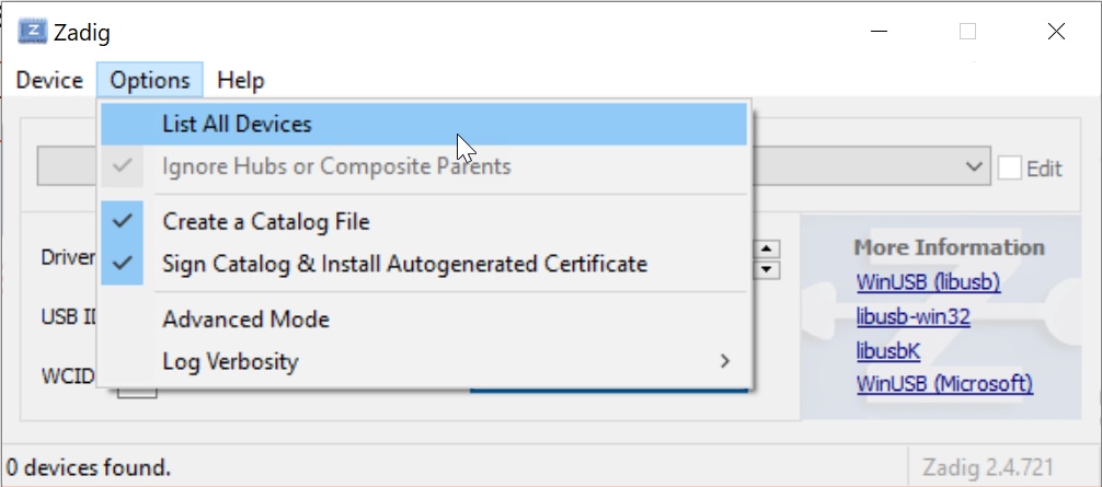
As part of the installation, the software will also install a utility called Zadig which is used to associate a particular driver with the Cypress chip. Run that utility, and plug in LISA. Click on Options -> List All Devices, and look for the USB device with the name Cypress FX2LP No EEPROM Device.
It should have USB ID 04B4 8613. Once you’ve found it, click on the button labelled Install Driver, or Replace Driver (it depends on if there is already some driver on your PC that needs to be overridden). Once you’ve done that, Zadig freezes for about half a minute and then displays a success message.
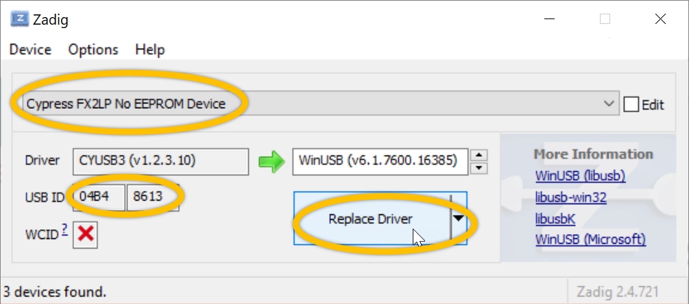
Now Zadig can be closed, and it doesn’t need to be used again.
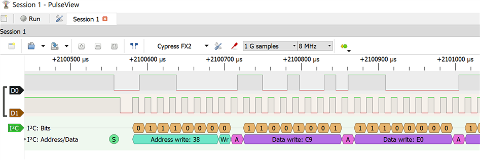
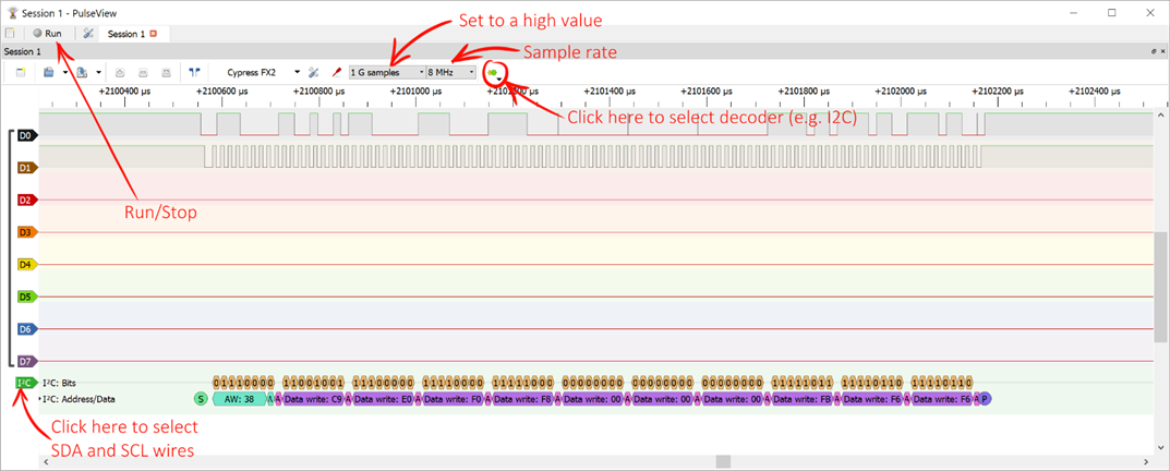
To use the logic analyzer, run the PulseView application. The screenshot below shows what it looks like.
Note: If PulseView generates a Failed to open device error, then there is a chance that you've got other devices that use the same Cypress chip, that you've in the past installed on your PC. I don't know of a solution except this one: uninstall the device from the Windows Device Manager, then unplug the device, then go to the C:/Windows/INF folder, and using a text editor that can 'Find in Files' (an example text editor is Microsoft Visual Code) and search for the text FX2LP. You'll find some files such as (say) oem1234.INF that contains this text. Delete all such files, as well as any corresponding .PNF file. Then, plug in the device and run Zadig and follow the steps as described earlier.
That screenshot was obtained by using LISA to examine the I2C bus from a Raspberry Pi, connected to a LCD module. The LED lights come in handy, to confirm that connections are made properly. The I2C bus is at logic ‘1’ most of the time and so the two LEDs are lit.
Summary
Making a high-speed USB 2.0 device is straightforward using Cypress FX2LP chips. The design here is compatible with open source PC application software, and provides isolation, some internal LEDs and also outputs for future use as a microcontroller or FPGA programmer. More work needs to be done to produce additional firmware and application software, to make full use of it.
I currently have a couple of spare PCBs, so if anyone wants them, let me know via a private message, and I’ll post them. If you get a chance to build it, or experiment with software, do share your findings : )
Top Comments
-

phoenixcomm
-
Cancel
-
Vote Up
0
Vote Down
-
-
Sign in to reply
-
More
-
Cancel
-

Jan Cumps
in reply to phoenixcomm
-
Cancel
-
Vote Up
0
Vote Down
-
-
Sign in to reply
-
More
-
Cancel
-

phoenixcomm
in reply to Jan Cumps
-
Cancel
-
Vote Up
0
Vote Down
-
-
Sign in to reply
-
More
-
Cancel
-

Jan Cumps
in reply to phoenixcomm
-
Cancel
-
Vote Up
0
Vote Down
-
-
Sign in to reply
-
More
-
Cancel
-

phoenixcomm
in reply to Jan Cumps
-
Cancel
-
Vote Up
0
Vote Down
-
-
Sign in to reply
-
More
-
Cancel
Comment-

phoenixcomm
in reply to Jan Cumps
-
Cancel
-
Vote Up
0
Vote Down
-
-
Sign in to reply
-
More
-
Cancel
Children