element14 Community
element14 Community
    Register Log In
  • Site
  • Search
  • Log In Register
  • About Us
  • Community Hub
    Community Hub
    • What's New on element14
    • Feedback and Support
    • Benefits of Membership
    • Personal Blogs
    • Members Area
    • Achievement Levels
  • Learn
    Learn
    • Ask an Expert
    • eBooks
    • element14 presents
    • Learning Center
    • Tech Spotlight
    • STEM Academy
    • Webinars, Training and Events
    • Learning Groups
  • Technologies
    Technologies
    • 3D Printing
    • FPGA
    • Industrial Automation
    • Internet of Things
    • Power & Energy
    • Sensors
    • Technology Groups
  • Challenges & Projects
    Challenges & Projects
    • Design Challenges
    • element14 presents Projects
    • Project14
    • Arduino Projects
    • Raspberry Pi Projects
    • Project Groups
  • Products
    Products
    • Arduino
    • Avnet Boards Community
    • Dev Tools
    • Manufacturers
    • Multicomp Pro
    • Product Groups
    • Raspberry Pi
    • RoadTests & Reviews
  • Store
    Store
    • Visit Your Store
    • Choose another store...
      • Europe
      •  Austria (German)
      •  Belgium (Dutch, French)
      •  Bulgaria (Bulgarian)
      •  Czech Republic (Czech)
      •  Denmark (Danish)
      •  Estonia (Estonian)
      •  Finland (Finnish)
      •  France (French)
      •  Germany (German)
      •  Hungary (Hungarian)
      •  Ireland
      •  Israel
      •  Italy (Italian)
      •  Latvia (Latvian)
      •  
      •  Lithuania (Lithuanian)
      •  Netherlands (Dutch)
      •  Norway (Norwegian)
      •  Poland (Polish)
      •  Portugal (Portuguese)
      •  Romania (Romanian)
      •  Russia (Russian)
      •  Slovakia (Slovak)
      •  Slovenia (Slovenian)
      •  Spain (Spanish)
      •  Sweden (Swedish)
      •  Switzerland(German, French)
      •  Turkey (Turkish)
      •  United Kingdom
      • Asia Pacific
      •  Australia
      •  China
      •  Hong Kong
      •  India
      •  Korea (Korean)
      •  Malaysia
      •  New Zealand
      •  Philippines
      •  Singapore
      •  Taiwan
      •  Thailand (Thai)
      • Americas
      •  Brazil (Portuguese)
      •  Canada
      •  Mexico (Spanish)
      •  United States
      Can't find the country/region you're looking for? Visit our export site or find a local distributor.
  • Translate
  • Profile
  • Settings
Test & Tools
  • Technologies
  • More
Test & Tools
Blog Electronic DC Load - Design and Build to test PSU Project
  • Blog
  • Forum
  • Documents
  • Files
  • Members
  • Mentions
  • Sub-Groups
  • Tags
  • More
  • Cancel
  • New
Join Test & Tools to participate - click to join for free!
  • Share
  • More
  • Cancel
Group Actions
  • Group RSS
  • More
  • Cancel
Engagement
  • Author Author: Robert Peter Oakes
  • Date Created: 2 Jun 2015 5:14 AM Date Created
  • Views 10384 views
  • Likes 7 likes
  • Comments 32 comments
  • modular_power_supply
  • electronic_dc_load
  • energy_power
  • dc_load
Related
Recommended

Electronic DC Load - Design and Build to test PSU Project

Robert Peter Oakes
Robert Peter Oakes
2 Jun 2015

Back tot he Main Modular Bench power System Project The Modular Bench Power Supply ++, The Essential DIY Build for Every EE Student and Old Timer alike...


I keep promising myself I will build an Electronic DC Load and have kept defering it, well no longer, I finally ot it designed and tested on a breadboard and will be following up with a completed unit in a project case


It can go way above 30V (60 to be precice and upto 5Amps), the MOSFET I used the IRFP064 is able to go to 70Amps but thats more than my wiring would stand and way more than i need so I designed the load to go upto 5Amps for now. All I need to do though is change the current sense resistor and it can easily become a 10Amp unit


For the heatsink I tested with a standard one but subsiquently found an old CPU heatsing with a Fan attached which looks like it will do a grand job of cooling the MOSFET etc so it will be the one I use in the build.


Testin showed I can load as little as 250mV and still control upto an Amp which is great and once im over 1V source voltage I can go all the way to 5Amps with ease.


Now you all know the math "Power = Volts * Amps) so therefor will know that at 30V an 5Amps theres 150W being dissipated in the MOSFET and thats a lot of heat. I am pretty sure the CPU heatsing even with the fan will still get pretty hot and I look forward to characturizing it once the bukd is done. till then I have no idea how well it will work but I am sure it will be better than the one I tested the circuit with


for now, here is the schamitic I came up with

image


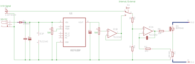
It will use between 12 and 24V for the DC in, has a REF02 Voltage reference to provide the manual setting via a 10 Turn pot and has a trimmer to accuratly set the top output to precisly 5A if so desired.

I also included a BNC input as an alternate control allowing a signal generator to control the load enabling many more test scenarious to be executed like transient response testing, noise response, Waveform based profile, pulse response etc.


The design does have a frequency limit before the output falls off of only a few hundred Hertz but that should be more than enough for this. It may be way better once it is off the bread board and the wiring is significanly shorter too but I wont be able to test that till the buld is complete. I will add a video to this blog once that is done and tested


anyway, enough banter, here is the video (Yes Im back to my 1+ hour videos... sorry I tried)

You don't have permission to edit metadata of this video.
Edit media
x
image
Upload Preview
image


Hope you enjoy


Thanks to Vishay Precision Group ( VPG) Bulk Metal Film division for their kind donation of the current sense resistors and precision metal film resistors used in the resistor divider part of the design. It takes the use of this project to the next level by bringing stability to the key parts of the design in the order of a few parts per million... oh yaaaa.

  • Sign in to reply

Top Comments

  • jw0752
    jw0752 over 9 years ago in reply to Former Member +3
    Hi Monica, Su Englais esta bien, mejor que mi Espanol. Don't worry too much about R-1. You can build one that will be accurate enough for this application. Just get a regular 0.1 ohm resistor and tie extra…
  • Robert Peter Oakes
    Robert Peter Oakes over 8 years ago in reply to stephanc +3
    I just checked on the first one ( IRL540N) and it is not even showing a DC spec, nothing more than a 10mS pulse This is the safe operating area.
  • Robert Peter Oakes
    Robert Peter Oakes over 9 years ago in reply to jw0752 +2
    Perfect jw0752 , that is exactly what I would have done if Vishay had not been so generous with some samples and is a perfect example of how to roll your own when the needs arise Thanks for sharing
  • alanthom
    alanthom over 6 years ago

    Dear Peter


    I know enough to be dangerous image

    Could you pse help.  I built your cct and had much fun.  I built the prototype on vero board and had one error.  Corrected and things are looking good but!!!   The MOSFET is driven on hard and no matter what I check, it short circuits the load.  To try and assist, here are some measurements:

    • Measured at pin 2 on REF02 = 12,17v - correct, using a 12v reg.
    • Measured on pin 6 of REF02 = 5,47v - correct
    • Measured on pin 7 of op amp = max 5,47v and min 0,592v adjusting POT 2 (10k lin)
    • With switch selecting internal (not signal external signal), measuring pin 3 of op amp = max 3,27v min 0v
    • Measured on pin 1 of op amp, before 10k res = 18,3v
    • Measured after res 10k, driving MOSFET = 18,3v constant.... irrespective of POT 1 (10k lin) and POT 2


    So the MOSFET is on hard IMHO.  This is a mistake on my board but I just don't seem to be able to identify the error in wiring.

    Any advice would be much appreciated.

    BTW - any news re a printed cct board...I'm still trying to learn KiCad.  A pdf of the track layout would help so much!


    But I do not expect you to do my job for me image

    Warm Regards out of Africa


    Alan


    • Cancel
    • Vote Up 0 Vote Down
    • Sign in to reply
    • More
    • Cancel
  • stephanc
    stephanc over 8 years ago in reply to Robert Peter Oakes

    Dear Peter


    I greatly appreciate your reply, help and advice.


    I’m testing and experimenting with your DC load circuit.


    Kind regards


    Stephan Cilliers


    Professional Engineer


    SC Consulting (Pty) Ltd  •   reg. no.: 2002/015924/07  •  Structural and Civil Engineers


    Suite 2, Canterbury Park, 67 Pres. Reitz Avenue, Bloemfontein  •  P.O. Box 29142, Danhof, 9310


    Cell: 0823717290  •  Tel:  051 406 3460  •  Fax: 051 406 3461  •  Email:  <mailto:stephan@scconsult.co.za> stephan@scconsult.co.za


       •   DIRECTOR: SP Cilliers PrEng BEng (Civil) MSAICE   •

    • Cancel
    • Vote Up 0 Vote Down
    • Sign in to reply
    • More
    • Cancel
  • Robert Peter Oakes
    Robert Peter Oakes over 8 years ago in reply to stephanc

    I just checked on the first one (IRL540N) and it is not even showing a DC spec, nothing more than a 10mS pulse

    This is the safe operating area.

    image

    • Cancel
    • Vote Up +3 Vote Down
    • Sign in to reply
    • More
    • Cancel
  • Robert Peter Oakes
    Robert Peter Oakes over 8 years ago in reply to stephanc

    I first take my design parameters and look for matching mosfet.

    1. Max Volts I need to handle + some wiggle room

    2. Max current I want to handle + wiggle room

    3. Total continuous power.


    This is where the fun starts. A large number of MOSFETS are characterized for switching (On or Off) and therefor their Power Rating reflects this and can even show things like 1KW, but when you dig deeper you find this is only good for a 10uS pulse so for a DC  load, almost totally useless.

    Just because a MOSFET is shown as a switching MOSFET does not mean it won't work for a linear application. the ones I listed can handle very high power in pulse mode but this drops rapidly in DC conditions. the latest two I mentioned

    the IXFN140N30P is a pulse mode MOSFET but also shows a good DC characteristics in the data sheet (300V, 110A, 0.024Ohms, Vgs(th) 3V)

    image

    the other one is actually DC characterized (Linear by design) but also shows pulse ratings that allow it to go to the 700W published power. (500V, 46A, 0.16Ohms, Vgs(th)3V)

    image

    I have not looked at the ones you listed yet but you can see, the DC figures are way under the pulse ones, but with some cleaver software one can allow more current at lower voltages and less at hi voltages to control the total power, also if the DC load is programed to support pulse loads then you can go way way higher (Assuming your wiring can handle it).


    So once I narrow down the available selections, I look at how to drive them, both the above support a Vgs(th) or 3V typical and max of only 5V so relatively easy to drive (Ignoring the capacitance of the gate image.


    I am no MOSFET expert but this is my initial sort criteria, also are the parts available for free from one of my sponsors comes into play of course.

    Another thing to consider is if your planning on paralleling up the mosfets to increase reliability and power capability, often you will find the Switching kind do not parallel well below a certain Vgs(th), their resistance goes down as they warm up, this can cause run away effects and the like, others have a much lower Vgs and will operate with the opposite effect. pretty much all MOSFETS of this type will have a transition between negative and positive temperature coefficient and its picking the one to suit your needs or designing arround the issue,


    This is a great resource I use, pretty sure this guy is an expert and he explains a lot of stuff way better than I can currently

    Kerry D. Wong » Blog Archive » Linear MOSFET and Its Use in Electronic Load


    Regards

    peter

    • Cancel
    • Vote Up +2 Vote Down
    • Sign in to reply
    • More
    • Cancel
  • stephanc
    stephanc over 8 years ago

    Dear Peter


    How do one go about selecting the MOSFET.
    I would have thought 5A 30V would be ample. The 70 Amps mosfet (IRFP064) has a very steep Id Vgs curve at low amps. Is this relevent?

    I would have thought a requirement would be a 'Linear MOSFET'. What does it mean?


    Would any of these be usable

    1. IRL540N

    2. IRF730B

    3. CEP83A3

    4. HRF3205

    5. S20N60C3S


    How would I parallel more that one to spread the heat better? Would you need some sort of balancing resister?


    Why did you use a 50K for the current adjustment pod and not a 10K?


    As you can see. I'm quite the novice!


    Kind regards

    Stephan

    • Cancel
    • Vote Up +1 Vote Down
    • Sign in to reply
    • More
    • Cancel
>
element14 Community

element14 is the first online community specifically for engineers. Connect with your peers and get expert answers to your questions.

  • Members
  • Learn
  • Technologies
  • Challenges & Projects
  • Products
  • Store
  • About Us
  • Feedback & Support
  • FAQs
  • Terms of Use
  • Privacy Policy
  • Legal and Copyright Notices
  • Sitemap
  • Cookies

An Avnet Company © 2025 Premier Farnell Limited. All Rights Reserved.

Premier Farnell Ltd, registered in England and Wales (no 00876412), registered office: Farnell House, Forge Lane, Leeds LS12 2NE.

ICP 备案号 10220084.

Follow element14

  • X
  • Facebook
  • linkedin
  • YouTube