element14 Community
element14 Community
    Register Log In
  • Site
  • Search
  • Log In Register
  • Community Hub
    Community Hub
    • What's New on element14
    • Feedback and Support
    • Benefits of Membership
    • Personal Blogs
    • Members Area
    • Achievement Levels
  • Learn
    Learn
    • Ask an Expert
    • eBooks
    • element14 presents
    • Learning Center
    • Tech Spotlight
    • STEM Academy
    • Webinars, Training and Events
    • Learning Groups
  • Technologies
    Technologies
    • 3D Printing
    • FPGA
    • Industrial Automation
    • Internet of Things
    • Power & Energy
    • Sensors
    • Technology Groups
  • Challenges & Projects
    Challenges & Projects
    • Design Challenges
    • element14 presents Projects
    • Project14
    • Arduino Projects
    • Raspberry Pi Projects
    • Project Groups
  • Products
    Products
    • Arduino
    • Avnet & Tria Boards Community
    • Dev Tools
    • Manufacturers
    • Multicomp Pro
    • Product Groups
    • Raspberry Pi
    • RoadTests & Reviews
  • About Us
    About the element14 Community
  • Store
    Store
    • Visit Your Store
    • Choose another store...
      • Europe
      •  Austria (German)
      •  Belgium (Dutch, French)
      •  Bulgaria (Bulgarian)
      •  Czech Republic (Czech)
      •  Denmark (Danish)
      •  Estonia (Estonian)
      •  Finland (Finnish)
      •  France (French)
      •  Germany (German)
      •  Hungary (Hungarian)
      •  Ireland
      •  Israel
      •  Italy (Italian)
      •  Latvia (Latvian)
      •  
      •  Lithuania (Lithuanian)
      •  Netherlands (Dutch)
      •  Norway (Norwegian)
      •  Poland (Polish)
      •  Portugal (Portuguese)
      •  Romania (Romanian)
      •  Russia (Russian)
      •  Slovakia (Slovak)
      •  Slovenia (Slovenian)
      •  Spain (Spanish)
      •  Sweden (Swedish)
      •  Switzerland(German, French)
      •  Turkey (Turkish)
      •  United Kingdom
      • Asia Pacific
      •  Australia
      •  China
      •  Hong Kong
      •  India
      •  Japan
      •  Korea (Korean)
      •  Malaysia
      •  New Zealand
      •  Philippines
      •  Singapore
      •  Taiwan
      •  Thailand (Thai)
      •  Vietnam
      • Americas
      •  Brazil (Portuguese)
      •  Canada
      •  Mexico (Spanish)
      •  United States
      Can't find the country/region you're looking for? Visit our export site or find a local distributor.
  • Translate
  • Profile
  • Settings
Test & Tools
  • Technologies
  • More
Test & Tools
Blog OpAmp as Schmitt-trigger
  • Blog
  • Forum
  • Documents
  • Files
  • Members
  • Mentions
  • Sub-Groups
  • Tags
  • More
  • Cancel
  • New
Join Test & Tools to participate - click to join for free!
  • Share
  • More
  • Cancel
Group Actions
  • Group RSS
  • More
  • Cancel
Engagement
  • Author Author: Jan Cumps
  • Date Created: 25 Jan 2025 6:29 PM Date Created
  • Views 9931 views
  • Likes 16 likes
  • Comments 23 comments
  • art of electronics
  • opamp
  • schmitt-trigger
Related
Recommended

OpAmp as Schmitt-trigger

Jan Cumps
Jan Cumps
25 Jan 2025

A Schmitt-trigger is a circuit that turns a non-perfect digital signal into a clean one. It has 2 main functions:

  • recreate a good fast ramp for signals that have lost their oomph (or never had clean fast edges). 
  • provide a bit of hysteresis, so that signals with significant noise can be restored to proper high and low

There was a recent design of shabaz that uses Schmitt-triggers:  Brush and Large-Area Multi-Meter Probes for PCB Reverse-Engineering: A DIY Approach! . The Art of Electronics (AOE) happens to explain that very circuit. A good excuse to check it out.

image
image source: The Art of Electronics 3rd edition p. 237 - fair use

Schmitt-triggers have a set level where they consider a signal high or low. The main difference with a comparator circuit, is that they also introduce hysteresis. Output will switch when the input reaches a particular level, but it will not switch again until the input has dropped below a different, lower, input level. An engineer will define the two levels so, that the noise on the input will never cause a state flip.

image

image source: TI Application Brief Understanding Schmitt Triggers - fair use

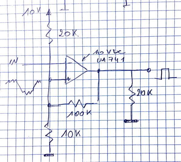
For this post, I'm recreating the AOE design based on an OpAmp (identical to Shabaz', just with different levels and operating voltage), The only change I made is the desired voltage level. I brought that down from  5 V to approx. 3.3 V, because that's in the range of my signal generator. I use the very common UA741 in this design, because I have a through-hole one. In a real design, you'd probably use a more modern one that can work on lower voltages, and can drive its output to the rails. And is faster (see jc2048 ' comment).

This is an inverting design. The output drives low when the input is high.

The circuit

It's virtually the same as the AOE design. But R1 is 20K instead of 10K, OpAmp voltage 10 V. 
image


image
images: the actual circuit that I set up on a breadboard.

Results

Test with an input that is noisy, and migrates to both upper and lower levels multiple times:

image
image source: the design successfully cleans up a noisy test signal from my waveform generator

The yellow trace is the input. I have chosen a signal that is noisy on both low and high level. I've set it so that it has glitches on both sides of the hysteresis range. The magenta trace is the output. It's a nice "digital" signal, with fast edges and little noise. Because I used the imperfect UA741, signal does not reach ground or VCC. The Blue trace is the set point. You can clearly see that the output level influences the comparison point.

Operation: this is an OpAmp with positive feedback. R3 feeds the output back to the + input. That "escalates" the OpAmp. When the input crosses the set point, it immediately goes to the rail voltage (or as close as it can get to it).

R3 also has another effect: It influences the set point, because it is either connected to the positive or ground rail. When output is low, R3 will pull the set point down a little. When output is high, it will pull it up somewhat. That's what generates the hysteresis. Set point and hysteresis width are function of the 3 resistors values (and by how close the OpAmps can drive to the rails).

  • Sign in to reply
  • shabaz
    shabaz over 1 year ago

    Excellent post, and very clear-to-follow explanation. I'm not sure I've ever seen an explanation that showed the set point in the 'scope traces, which helps understand it a lot.

    It's so easy to accidentally assume that an op-amp as basic comparator is all that is needed, whereas the hysteresis can greatly improve it.

    • Cancel
    • Vote Up 0 Vote Down
    • Sign in to reply
    • More
    • Cancel
  • genebren
    genebren over 1 year ago

    I remember learning OpAmp circuits back in the mid 70’s and the comparator with hysteresis was one my favorite circuits. On my first job out of college, my first improvement to an existing design had to do with a poorly designed comparator circuit with insufficient hysteresis. It real felt good to solve an issue so early in my career (within the first month out of school and on the job).

    • Cancel
    • Vote Up 0 Vote Down
    • Sign in to reply
    • More
    • Cancel
  • DAB
    DAB over 1 year ago

    Great post Jan.

    • Cancel
    • Vote Up 0 Vote Down
    • Sign in to reply
    • More
    • Cancel
<
element14 Community

element14 is the first online community specifically for engineers. Connect with your peers and get expert answers to your questions.

  • Members
  • Learn
  • Technologies
  • Challenges & Projects
  • Products
  • Store
  • About Us
  • Feedback & Support
  • FAQs
  • Terms of Use
  • Privacy Policy
  • Legal and Copyright Notices
  • Sitemap
  • Cookies

An Avnet Company © 2026 Premier Farnell Limited. All Rights Reserved.

Premier Farnell Ltd, registered in England and Wales (no 00876412), registered office: Farnell House, Forge Lane, Leeds LS12 2NE.

Follow element14

  • X
  • Facebook
  • linkedin
  • YouTube