|
A little OpAmp circuit to turn a balanced signal into an unbalanced one. This is the circuit that jc2048 shows in my previous article. |
The circuit
The concept is very simple. An OpAmp that can accept a balanced signal on its + and - inputs. At the output, it serves the same signal unbalanced, referenced to ground.
I've used 33 kΩ resistors. 5%, but from the same batch. At this point, I haven't checked how well matched they are, but given that they are 5%, that isn't relevant.
As balance input, I used an isolated function generator, 520 mVRMS, 1 kHz sinus. The generator has to be galvanically isolated from power supply and oscilloscope. A battery or power brick powered one usually works. If the generator output is grounded, it will not be able to generate a balanced signal.
Probing
Probing the balanced input signal
There's a chicken-and-egg situation at the input - for this blog only, not in real life. This is a circuit to measure balanced signals, and render its unbalanced representation. But if you put a normal probe at the input, the probe ground will disturb the balanced input. As suggested in the previous blogs, there are several solutions to measure that (one of them being this circuit). I'll use a differential probe to measure that input signal.
Probing the unbalanced output
That's easy. The output is unbalanced (ground referenced). So you can just use a common oscilloscope probe, with the probe ground connected to the circuit ground.

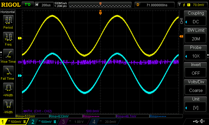
Channel 1 is the input, probed with the differential probe. Channel 2 the output with a common x10 probe.
The purple math channel is the difference between output and input.


Top Comments
-

shabaz
-
Cancel
-
Vote Up
0
Vote Down
-
-
Sign in to reply
-
More
-
Cancel
-

jc2048
in reply to shabaz
-
Cancel
-
Vote Up
0
Vote Down
-
-
Sign in to reply
-
More
-
Cancel
-

jc2048
in reply to shabaz
-
Cancel
-
Vote Up
0
Vote Down
-
-
Sign in to reply
-
More
-
Cancel
-

Jan Cumps
in reply to jc2048
-
Cancel
-
Vote Up
0
Vote Down
-
-
Sign in to reply
-
More
-
Cancel
-

Jan Cumps
in reply to jc2048
-
Cancel
-
Vote Up
0
Vote Down
-
-
Sign in to reply
-
More
-
Cancel
-

jc2048
in reply to Jan Cumps
-
Cancel
-
Vote Up
0
Vote Down
-
-
Sign in to reply
-
More
-
Cancel
-

Jan Cumps
in reply to jc2048
-
Cancel
-
Vote Up
0
Vote Down
-
-
Sign in to reply
-
More
-
Cancel
Comment-

Jan Cumps
in reply to jc2048
-
Cancel
-
Vote Up
0
Vote Down
-
-
Sign in to reply
-
More
-
Cancel
Children